![[Datsun 1200 encyclopedia]](/wiki/upload/wiki.png)
Revision as of 06:53, 31 May 2009
The lighting circuits generally use Green wires:
- G - IG-hot from Fuse Box
- GY - Brake lights (stop lamps)
- GL - running lights (parking lights)
- GB - R.H. Turn Signal + running lights
- GR - L.H. Turn Signal + running lights
Turn Signals: The T/S path is as follows: From the IG side of the Fuse Box through the 10A "M" terminal (G wire) to the Four-Way Flasher Switch (Hazard Switch). This switch is normally off and so routes power through G wire to T/S Flasher Unit. This means one side of the T/S Flasher is normally HOT -- but only if the key is ON. From the T/S Flasher unit the power goes to the T/S Switch on the column. In the center position of course the power stops here. But move the switch to right or left, and the power is fed to the Left or Right circuits to power all the exterior bulbs and the two dash bulbs. The T/S Flasher Unit causes the power to start/stop resulting in flashing.
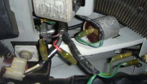
- NILES Hazard flasher bolts to right side of column brace (G/L, G/W)
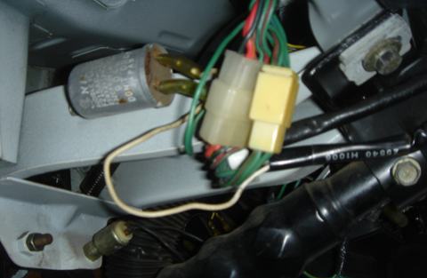
- NILES Turn Signal flasher bolts to left side of column brace
- W wire goes into steering column harness, up to the T/S switch
- G is the other wire
Front Side Marker lamp connector
| B | Ground | body connection |
| GB | (R.H. side only) | GL wire (non-flashing) |
| GR | (L.H. side only) | GL wire (non-flashing) |
Front Parking T/S Lamp connector
| B | Ground | body connection |
| GB | Right-side T/S circuit
(R.H. side only) | From right-side (GB) T/S circuit |
| GR | Left-side T/S circuit
(L.H. side only) | From left-side (GR) T/S circuit |
| GL | Dedicated parking lamp circuit | From GL circuit |
Dimmer Switch (in T/S & Light Switch unit on steering column)
(T/S section of switch listed here)
| ? | T/S hot feed | | GB | Right-side T/S circuit | <li>To Right-side (GB) T/S circuit
| <li>To Instrument panel GR wire (right T/S lamp) GR | Left-side T/S circuit | <li>To Left-side (GR) T/S circuit
| <li>To Instrument panel GR wire (left T/S lamp) [edit] Brake lightsBrake lights (STOP lamps) -- thankfully -- are simply connected on the B110. At the rear light boxes, the GY wires connect to the main harness GY circuit. This is connected to the "Stop Lamp Switch" at the brake pedal. The other side of this switch (both are YG wires) is connected to Fuse Box GY wire ("H" terminal 15A always-hot). So brake lights work when key is off.
|