Exhaust Gas Recirculation (EGR) was first used starting with 1974 B-210 (North American B210) models. Australia 1200 utes got EGR in 1982. Japan 1200 trucks got it in 1989. It recirculates a small portion of the exhaust back into the combustion chamber. Although this dilutes the the air/fuel mixture (reducing performance), it reduces burning temperatures resulting in drastic reductions of Oxides of Nitrogen (NOx).
Contents |
Overview
EGR is a key emission control technology. Even the new 2012 models use EGR, although now it can be effected by variable camshaft overlap and engine computer control. Datsuns use an early version of EGR which is heavy-handed regarding performance, but really does clean up the air.
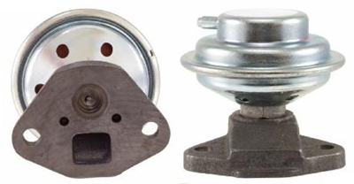
The EGR valve simply mixes a little exhaust into the intake manifold.

Varying amounts of exhaust gas are let in by the pintle valve, which travel to the inlet manifold via the large square opening.
How much exhaust is recircutated depends on the vacuum signal, which comes from a port high on the carburetor. This is not the distributor vacuum advance signal, but rather it requires a signal that does the opposite: gets stronger as the throttle is opened.
EGR does not work at full throttle, due to the vacuum throttle. So it won't hurt peak HP. It only affect part-throttle performance. It also does not activate at idle. It only takes effect in-between idle and full throttle.
For a detailed explanation of EGR, see the AutoZine Technical School article.
Basic EGR System
Datsun EGR consists of:
- Exhaust manifold with an EGR port tube
- Intake manifold machined to take an EGR body adapter
- EGR passage body, which bolts to the intake manifold
- EGR valve, which bolts to the body
- One or more switches
- Vacuum hoses
Generally speaking, the more complex the EGR system, the better. The complexity was to use less recirculation which is good for performance and fuel economy. This simplest implementations affected performance worse. There is little downside to this complexity because generally if anything fails, EGR fails to work and so doesn't hurt performance.
Models using the simplest basic system include:
- 1975 B210 AT North America (FED+CAL+CAN)
- 1975 B210 MT.CAL (MT.FED and MT.CAN add more switches)
- 1982 CAN all engines (A12A, A14, A15)
Exhaust Manifold
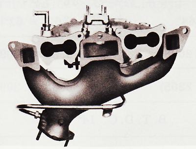
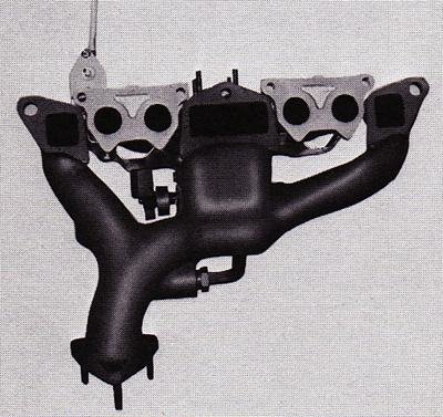
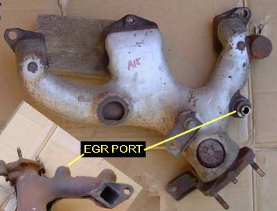
The only modification to the Exhaust Manifold to enable EGR is the casting is changed to add a threaded port to which a tube is fastened. The tube goes up to the EGR Valve.
First EGR (1974) -- tube goes behind manifold

Variations consist of:
- Size of the EGR port (diameter of hole and thread size)
- Location. Early engine had it come straight out of the manifold outlet, while newer ones have it pointing almost up
There are also Tube variations: Some tubes are threaded on both ends, others threaded only on the manifold end
Intake Manifold
Intake Manifold has a specially machined flat area where the EGR Body bolts. Nissan calls this adapter body the "EGR passage". In turn, the EGR Control Valve bolts to the body.
1981-1982 H95 EGR (valve not installed)

EGI
A14E and A15E EGI fuel injection engine manifolds use an EGR system.
Switches
These switches are to limit when the EGR works. Don't delete or bypass them otherwise your EGR will work full-time (not good).
Thermal Switch
This prevents EGR from working until the engine warms up. The switch only opens when the coolant exceeds 134F (57C).
This switch is your friend.
Thermal Vacuum Switch
From 1975, a simple, reliable engine-coolant Vacuum switching valve is used by most implementations. It threads into the cylinder head and is warmed by the engine coolant.
The switch has two ports. One hose comes from the carburetor signal, the other goes to the EGR valve.
Thermal Electric Switch
For the first year 1974, instead of the simple thermal vacuum switch, an engine-coolant electric switch was used along with a relay and an electrically-operated vacuum switch. This was replaced in 1975 by the simpler thermo-vacuum switch.
3-port Thermal Switch
This switch looks similar to the Thermal Vacuum Switching Valve, but has a third port which goes to the air cleaner. It bleeds off the carburetor vacuum signal, thus de-activating EGR. It is used in conjuction with a vacuum-delay valve in the hose that goes to EGR valve, which smooths out the reponse on quick throttle changes.
- 1982 FED & CAL models
Transmission Switch
Some models de-activated EGR when in nuetral or in top gear. This made use of the transmission Nuetral switch and transmission Top switch.
- 1975 Manual Transmission FED & CAN
VVT
Venturi Vacuum Transducer is used on later implementations to fine tune how much Recirculation is used. Instead of the crude early systems without VVT, the 1980s implementations use the VVT valve as an amplifier for input signals from backpressure and carburetor signal.
If you run EGR, then VVT is your friend.
History
1974: EGR fitted to North American B210.
== Australia
Japan
North America
1974: EGR first fitted to North American B210. It used a basic system, except the switch was a complicated electric system. This was the A13 engine.
1975: EGR continued on the new A14. Simpler 2-port Thermal Vacuum Switch replaced 1974's electric switch, relay, solenoid and wiring.

![[Datsun 1200 encyclopedia]](/wiki/upload/wiki.png)


