![[Datsun 1200 encyclopedia]](/wiki/upload/wiki.png)
Download: Datsun 1200 Competition Suspension Manual
Foreward
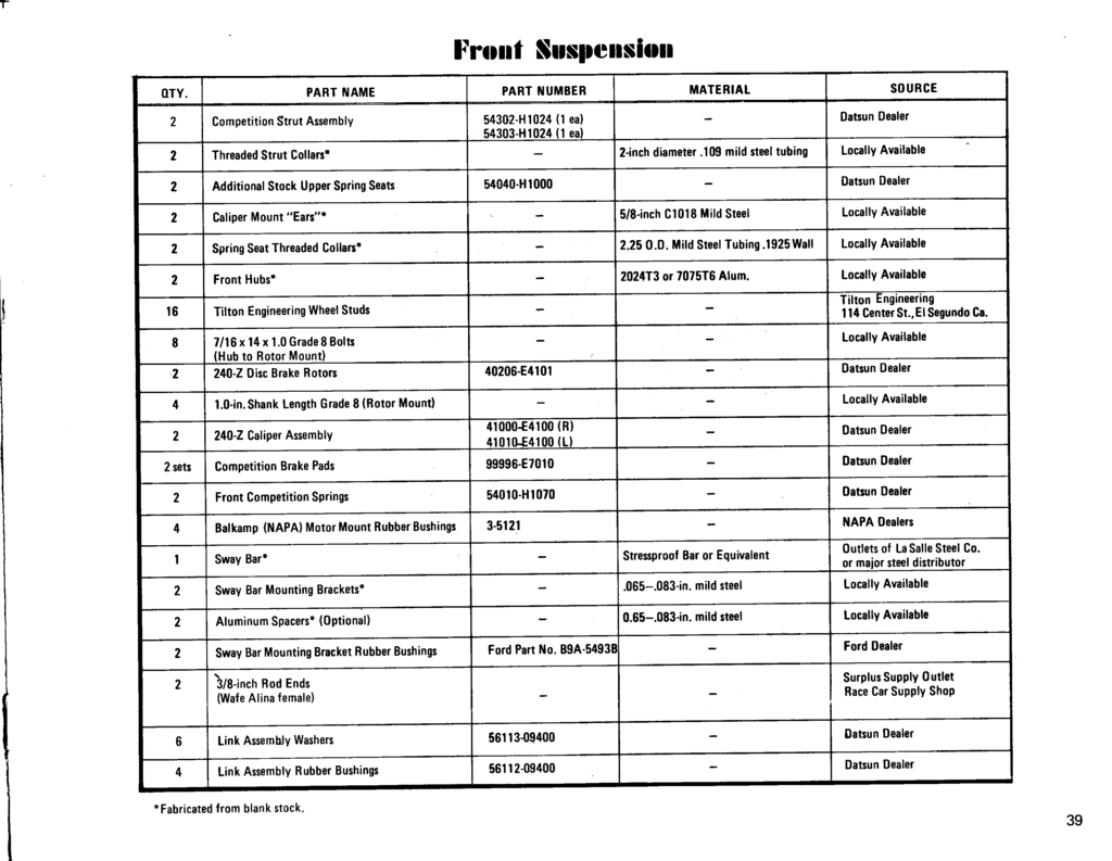
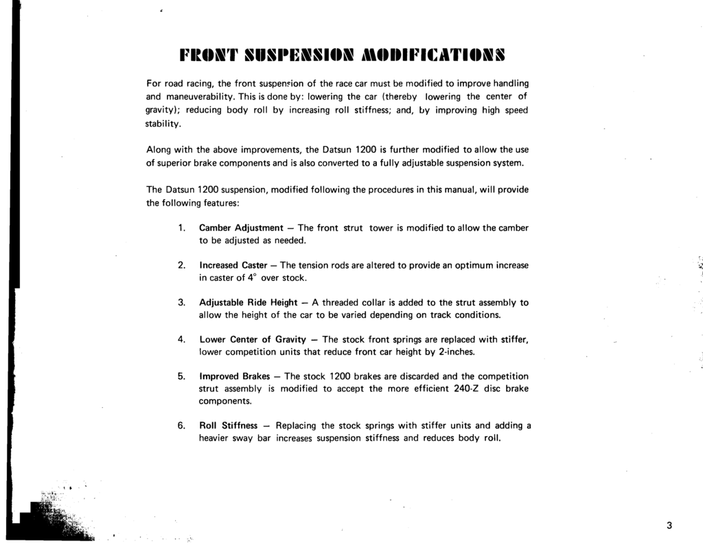
Front Suspension Modifications
For road racing, the front suspension of the race car must be modified to improve handling and maneuverability. This is done by: lowering the car (thereby lowering the center of gravity); reducing body roll by increasing roll stiffness; and, by improving high speed stability.Along with the above improvements, the Datsun 1200 is further modified to allow the use of superior brake components and is also converted to a fully adjustable suspension system.
The Datsun 1200 suspension, modified following the procedure in this manual, will provide the following features:
1. Camber Adjustment the front strut tower is modified to allow the camber to be adjusted as needed. 2. Increased Caster the tension rods are altered to provide an optimum increase in caster of 4° over stock.
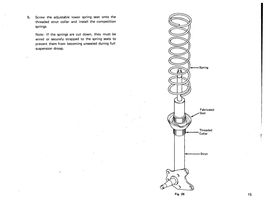
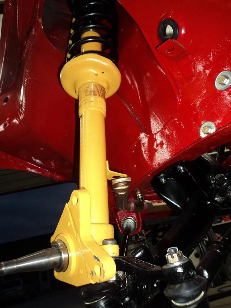
3. Adjustable Ride Height A threaded collar is added to the strut assembly to allow the height of the car to be varied depending on track conditions.
4. Lower Center of Gravity The stock front springs are replaced with stiff, lower competition units that reduce front car height by 2 inches.
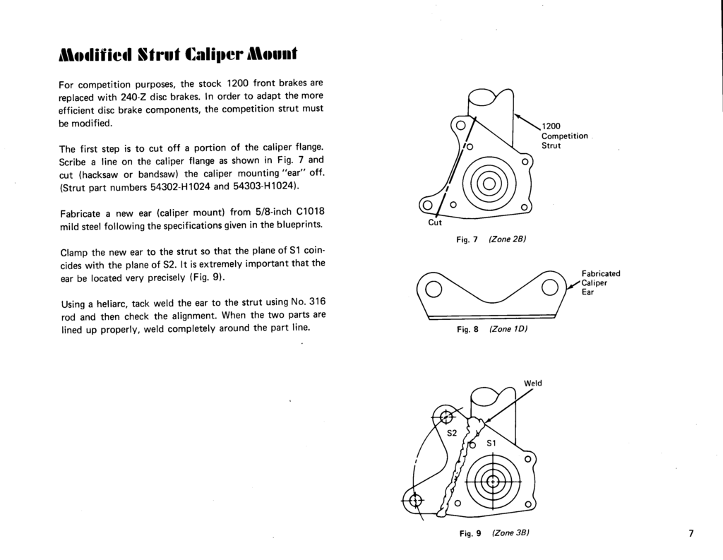
5. Improved Brakes The stock 1200 brakes are discard and the competition strut assembly is modified to accept the more efficient 240-Z disc brake components.
6. Roll Stiffness Replacing the stock springs with stiffer units and adding a heavier sway bar increases suspension stiffness and reduces body roll.
 Page 3
Front Camber Adjustment
See main article: Camber
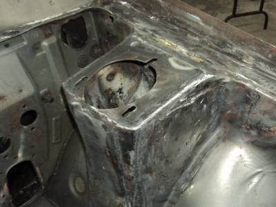
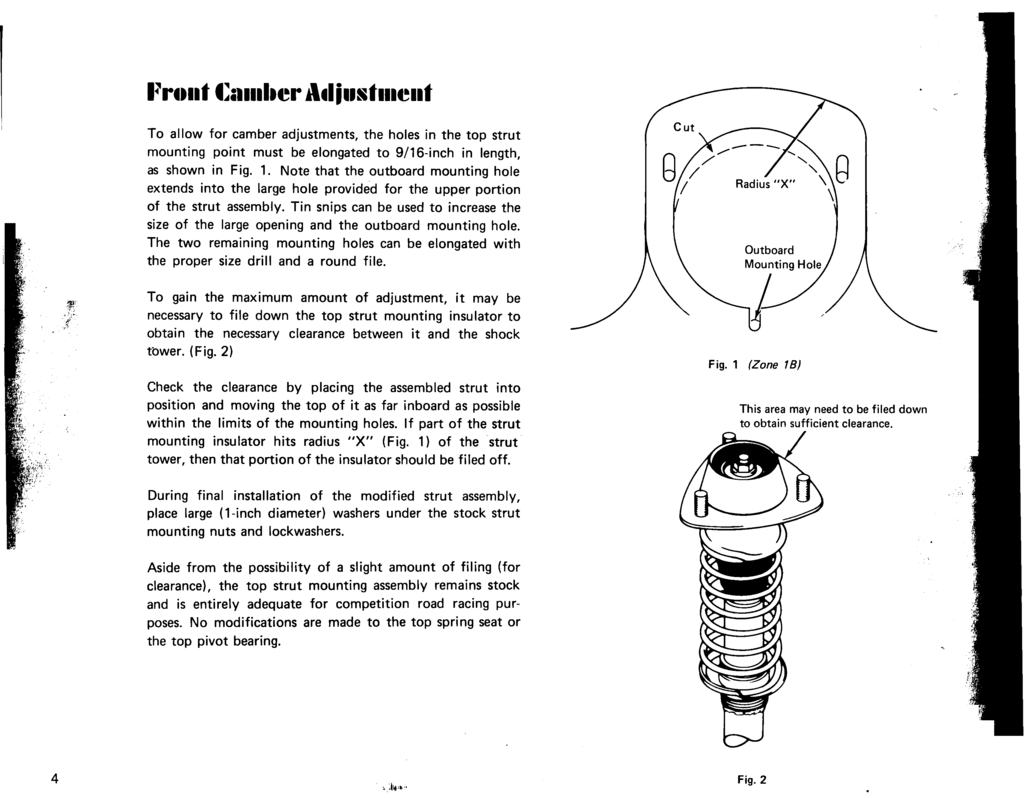
Front Camber AdjustmentTo allow for camber adjustments, the holes in the top strut mounting point must be elongated to 9/16-inch in length, as shown in Fig. 1. Note that the outboard mounting hole extends into the large hole provided for the upper portion of the strut assembly. Tin snips can be used to increase the size of the large opening and the outboard mounting hole. The two remaining holes can be elongated with the proper size drill and a round file.
To gain the maximum amount of adjustment, it may be necessary to file down the top strut mounting insulator to obtain the necessary clearance between it and the shock tower. (Fig. 2)
Check the clearance by placing the assembled strut into position and moving the top of it as far inboard as possible within the limits of the mounting holes. If part of the strut mounting insulator hits radius "X" (Fig. 1) of the strut tower, then that portion of the insulator should be filed off.
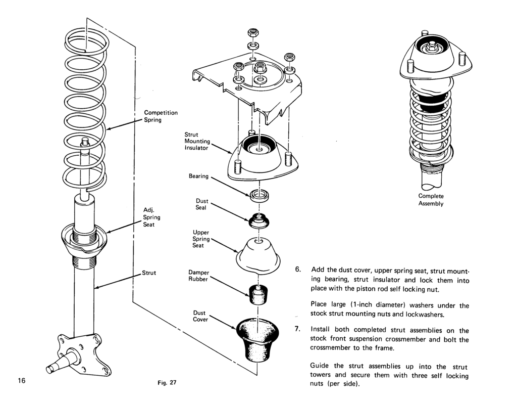
During final installation of the modified strut assembly, place large (1-inch diameter) washers under the stock strut mounting nuts and lockwashers.
Aside from the possibility of a slight amount of filing (for clearance), the top strut mounting assembly remains stock and is entirely adequate for competition road racing purposes. No modifications are made to the top spring seat or the top pivot bearing.
Fig. 1
Fig. 2
 page 4
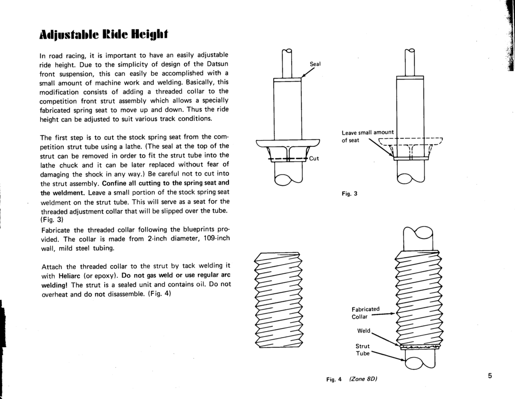
Adjustable Ride Height
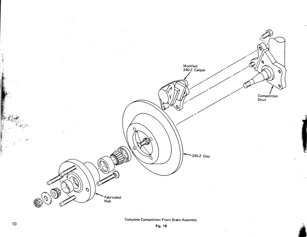
Modified Strut Caliper Mount
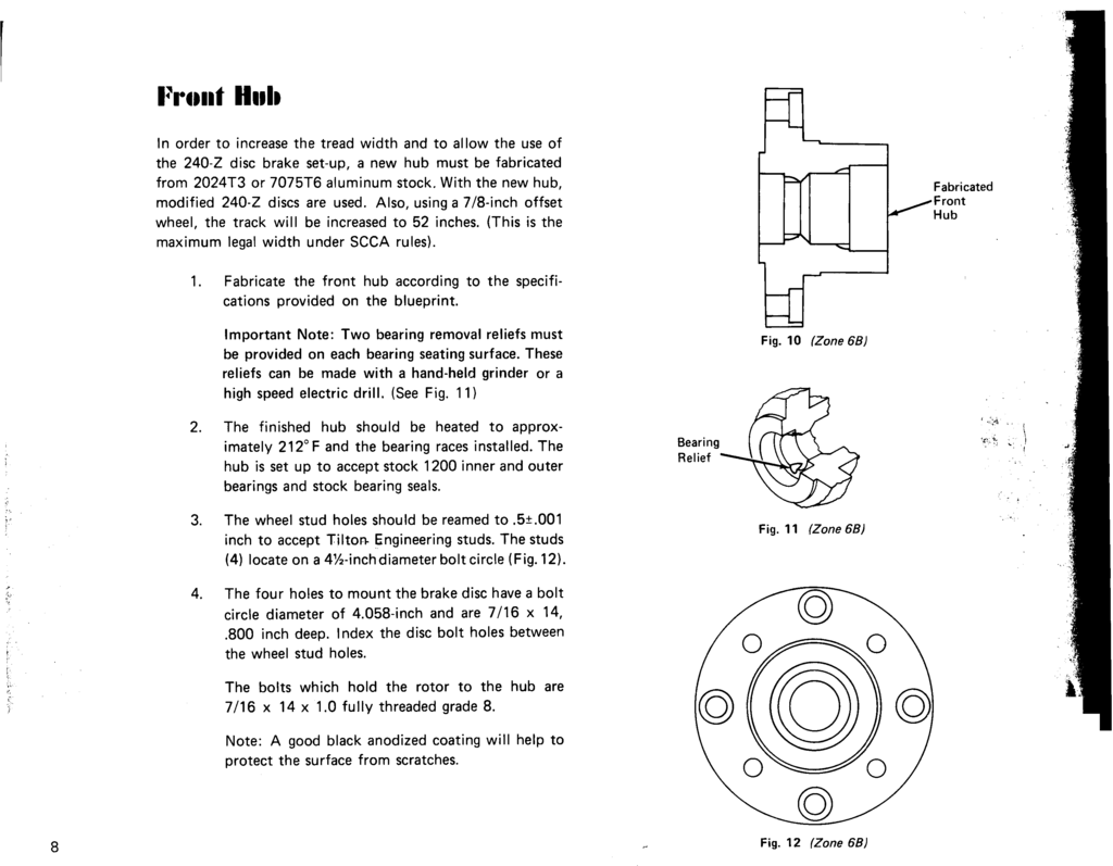
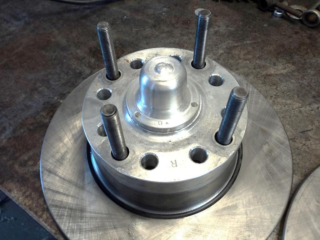
Front Hub
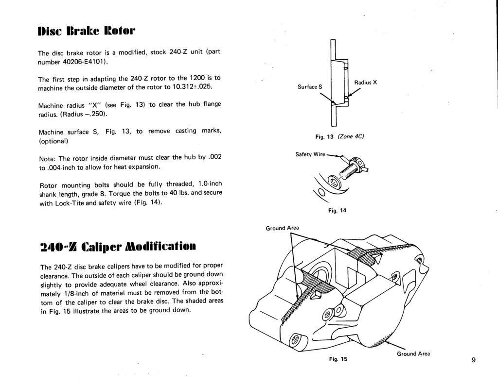
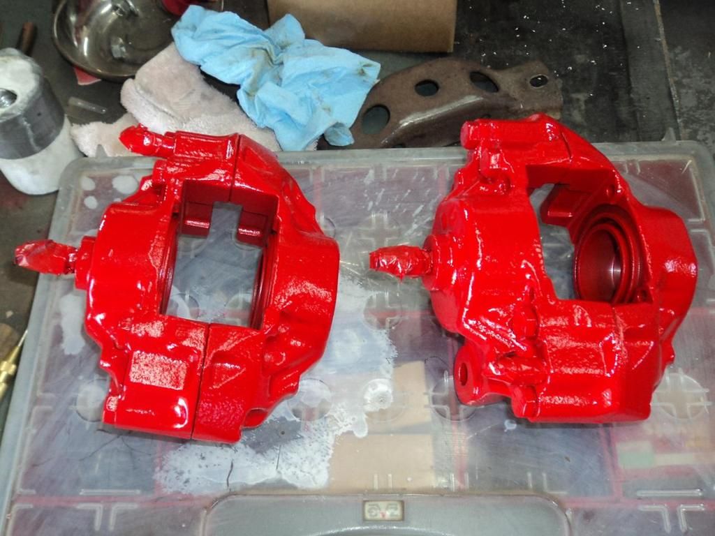
240-Z Caliper Modification
Front Springs
Lower Link and Steering Gear
The complete lower suspension link can be left stock. The inner chassis mount rubber bushing may also be left stock since it is very rigid and deflects a minimal amount while cornering.
The complete steering linkage assembly is adequate for competition purposes. This includes the steering gear box, tie rods, tie rod ends, all steering arms, idler arm assembly and the lower ball joint.
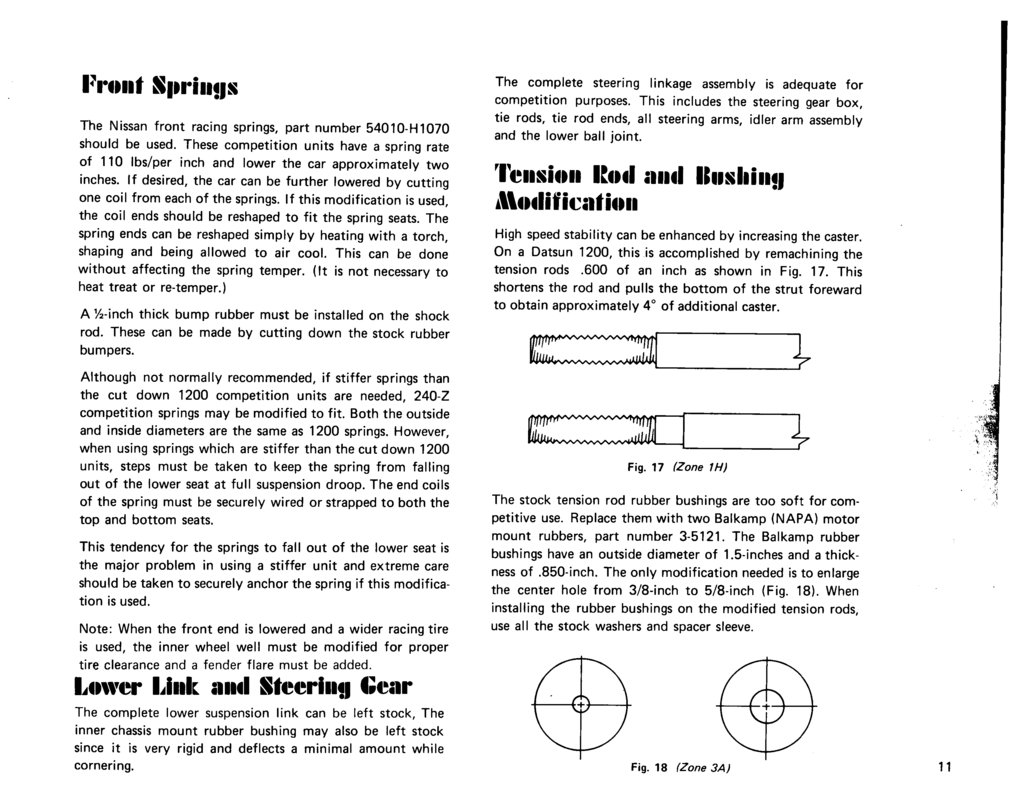
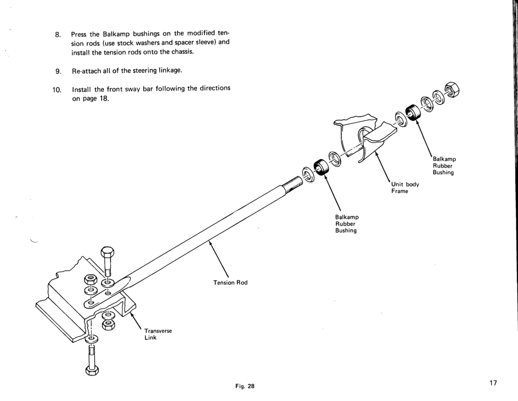
Tension Rod and Bushing Modification
Page 11
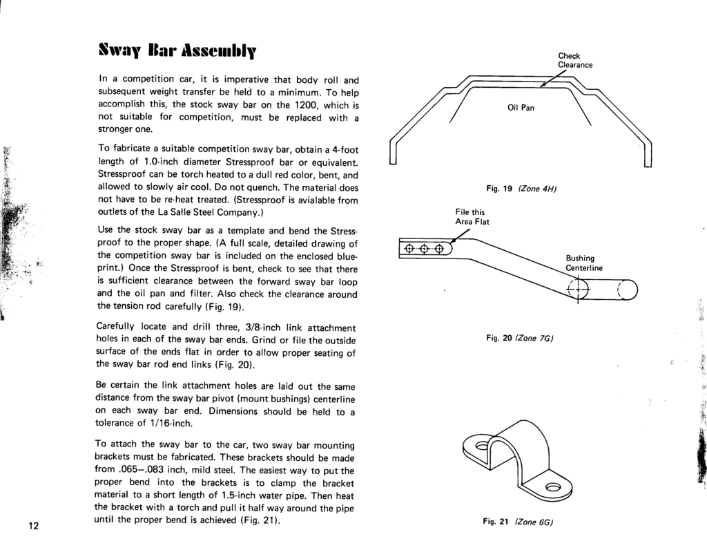
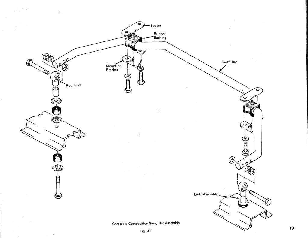
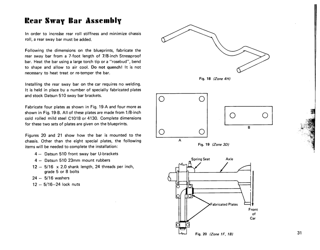
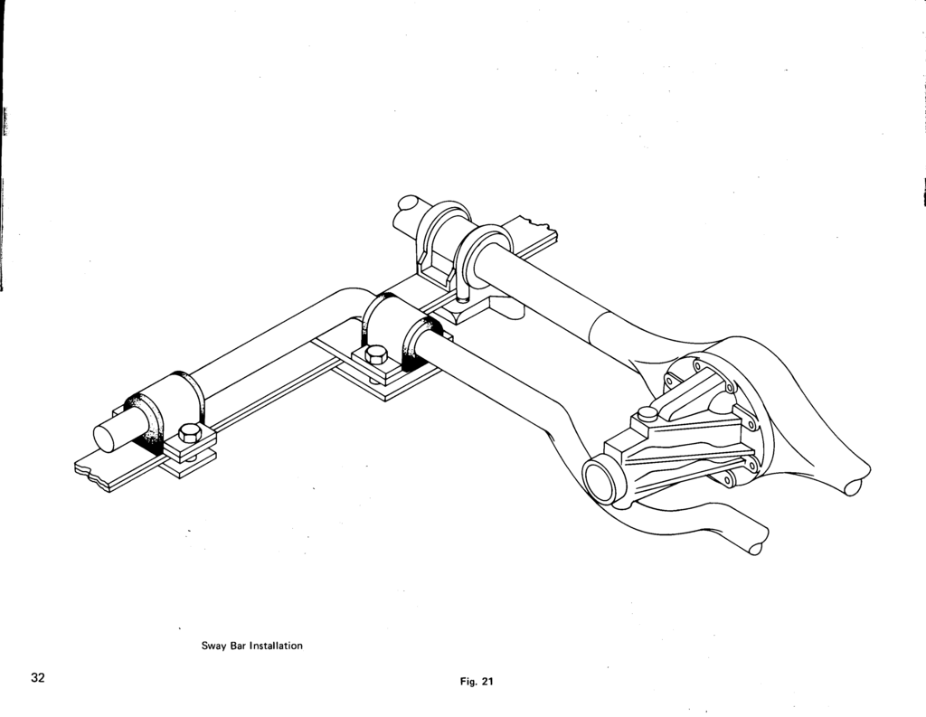
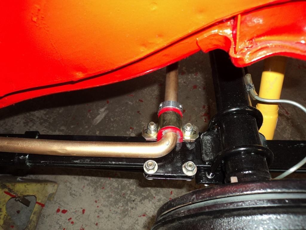
Sway Bar Assembly
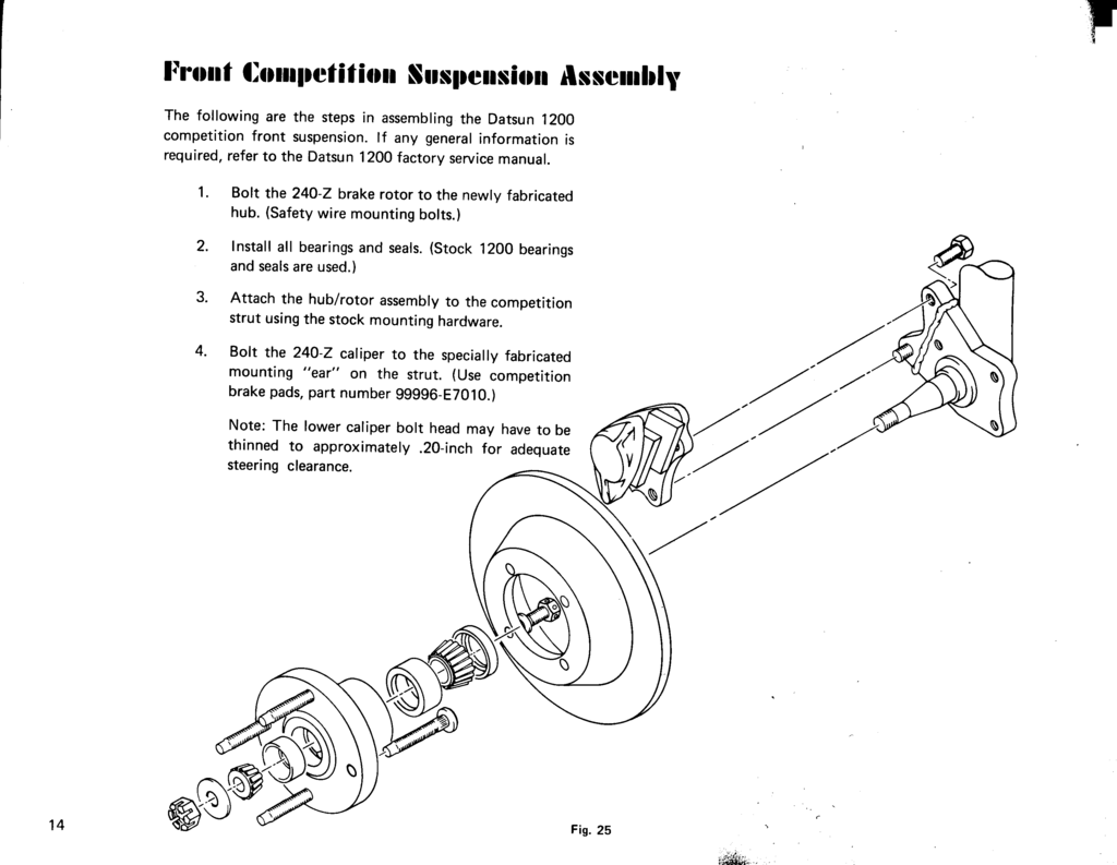
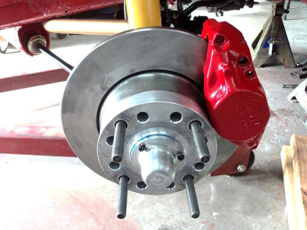
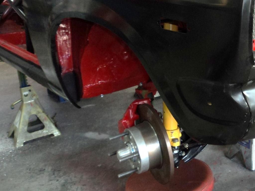
Front Competition Suspension Assembly
Sway Bar Installation
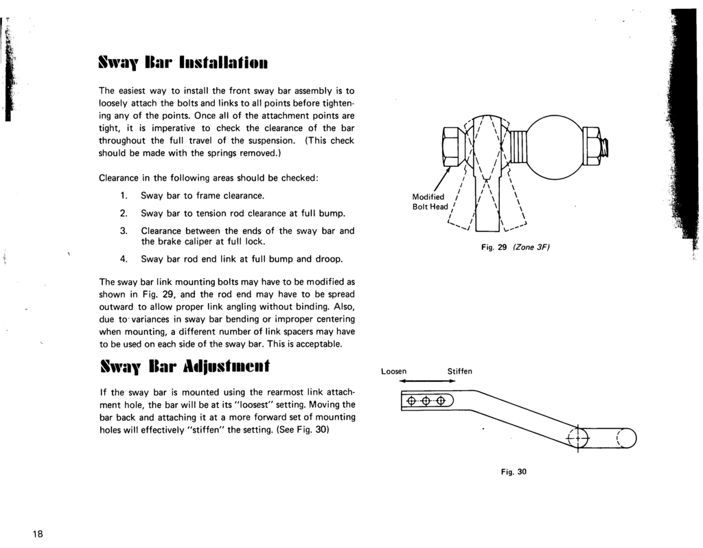
Sway Bar Adjustment
page 20 (blank page)

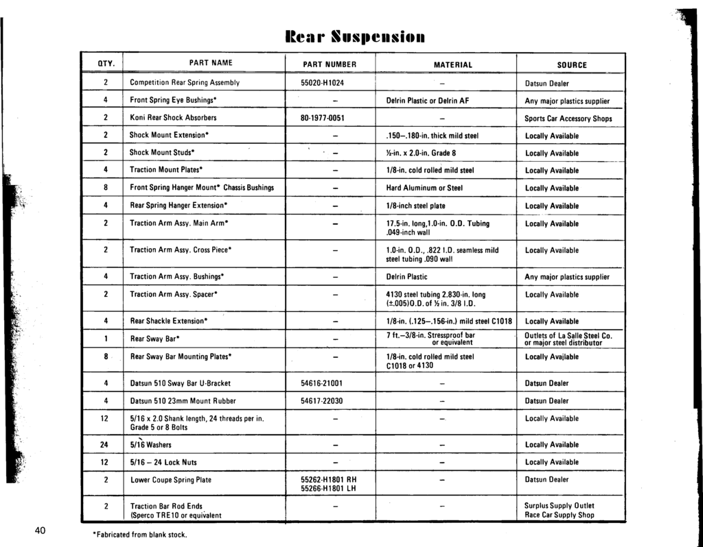
Rear Suspension Modifications
Like the front, the rear suspension must be modified to improve handling and maneuverability. Steps must also be taken to see that traction is improved to insure that all the available power "gets to the ground."In order to improve handling and traction, the modifications illustrated in this manual are designed to achieve the following results:
1. Control of lateral and fore-and-aft rear axle movement. 2. Prevent spring wrap-up and improve traction.
3. Increase spring rate.
4. Provide a fully adjustable suspension (shocks, ride height, roll stiffness).
5. Lower car height.Since the front and rear suspensions are dissimilar, different steps are needed to achieve the desired results in the rear. These modifications include:
1. Shocks and reworked lower shock mount. 2. Spring modification.
3. Front spring eye bushings.
4. Fron spring hanger chassis mount bushings.
5. Traction arm assembly.
6. Reworked rear spring shackle assembly.
7. Sway bar assembly.
 Page 21
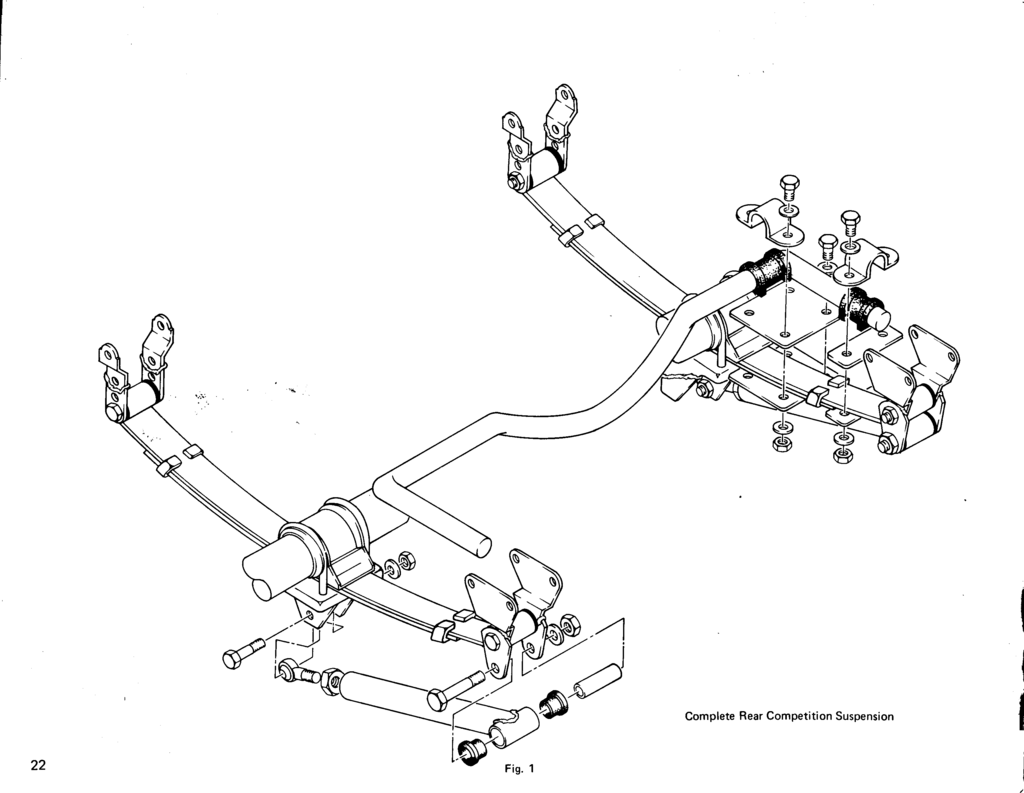
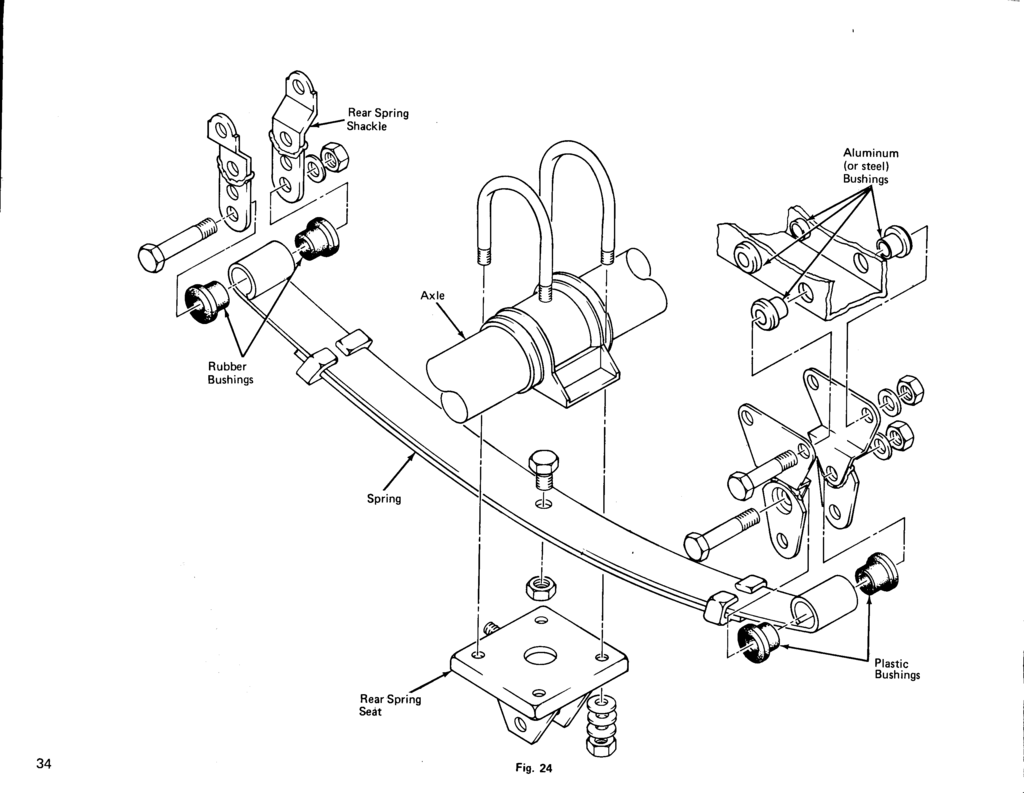
page 22 Fig. 1 Complete Rear Competition Suspension
Rear Spring Modification
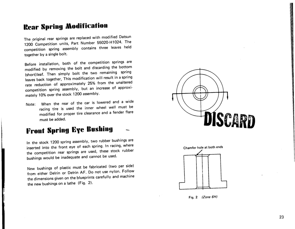
Front Spring Eye Bushing
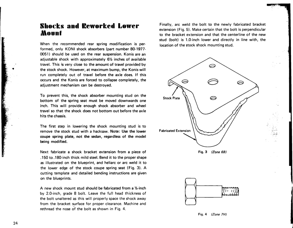
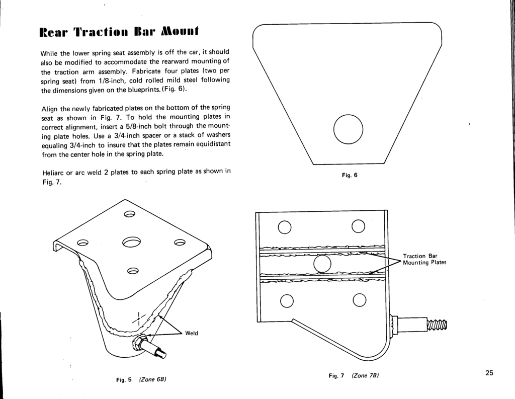
Shocks and Reworks Lower Mount
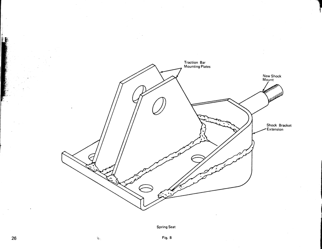
Rear Traction Bar Mount
Front Spring Hanger Mount Chassis Bushing
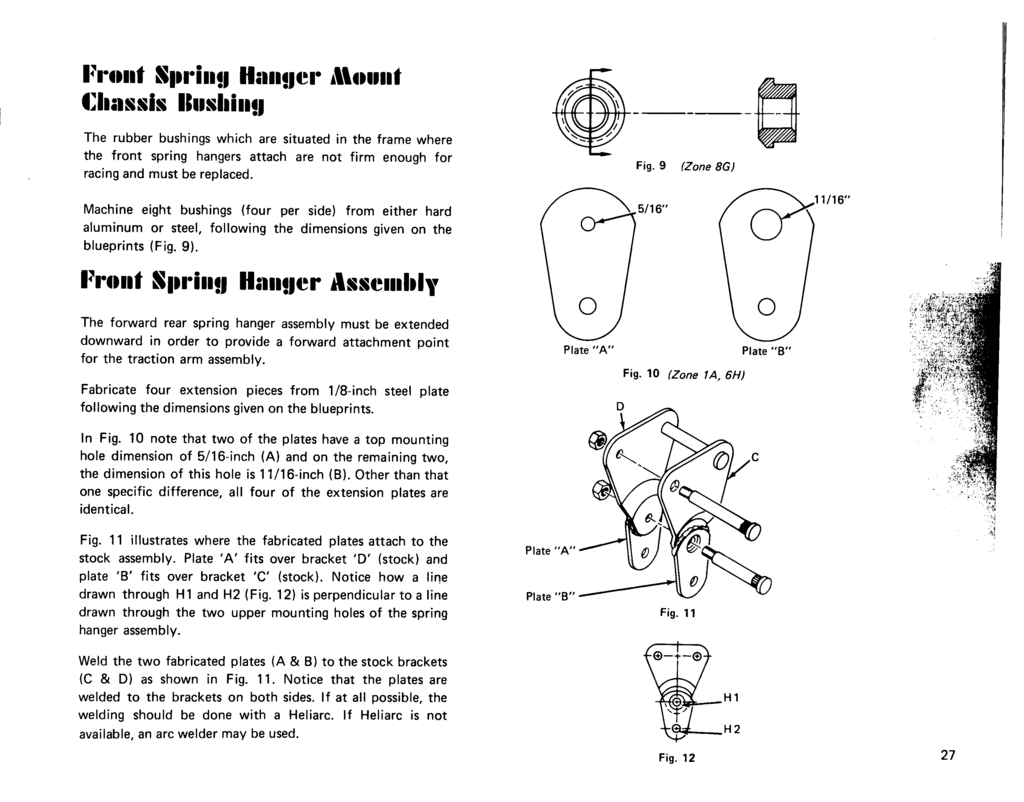
Front Spring Hanger Assembly
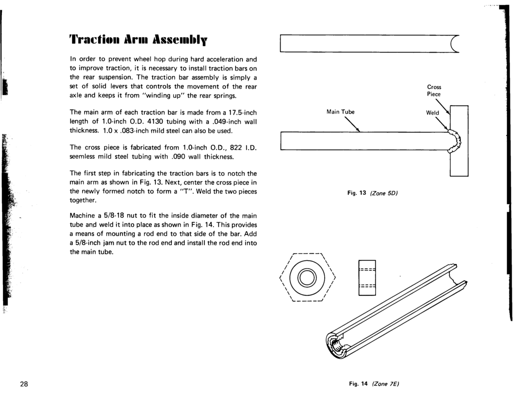
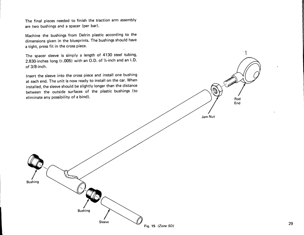
Traction Arm Assembly
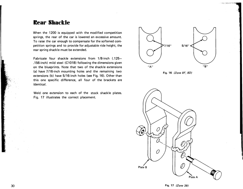
Rear Shackle
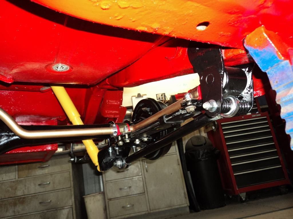
Rear Sway Bar Assembly
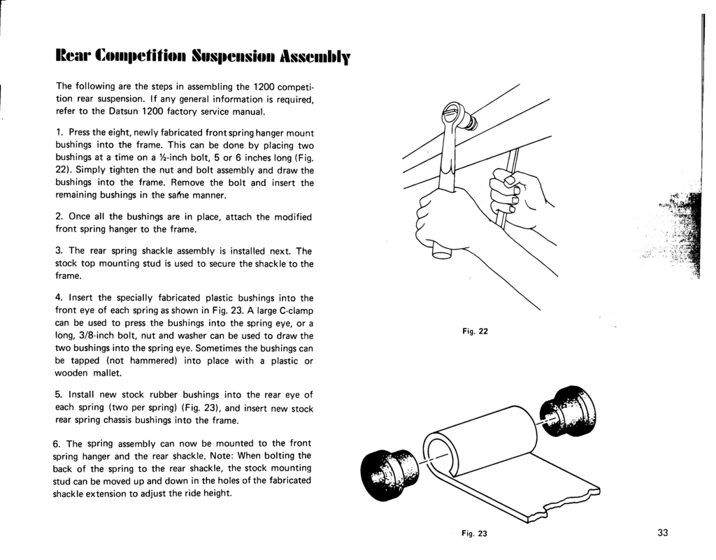
Rear Competition Suspension Assembly
Final Adjustments
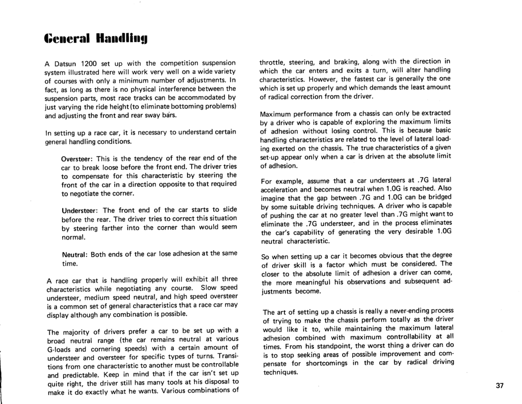
General Handling
page 37