![[Datsun 1200 encyclopedia]](/wiki/upload/wiki.png)
Some 1980-1982 Datsuns in Asia markets came with an OEM (factory) EFI system. Nissan called it "EGI" -- Electronic Gasoline Injection (日産 EGI). This is the "rare as" A14E Injection motor (インジェクション エンジン). At 92 horsepower it was far superior to the carbureted 80 hp A14/A15, in fact this was the most powerful A engine offered by Nissan, with more horsepower than the twin-carb GX Engine.
Contents |
Overview
92 PS @ 6000 rpm
A14E - 11.7 kgm @ 3600 rpm (85 ft lb)
A15E - 12.3 kgm @ 3600 rpm (89 ft lb)
Compression Ratio: 9.0
Regular unleaded gasoline
quote:
a friend of mine has a system that came on the A14 in the [N10?] M10 Pulsars (very first ones). The set up he got came from Singapore
The A14E engine came in:
- 1979-1981 N10 Langley (Pulsar) -- Asian markets
- 1978-up Feb - B310 Sunny 1400SGX-E Coupe -- Asian markets
A14E was available until October 1980. It was replaced by A15E in November 1980. The A15E is nearly identical but features a dual-outlet exhaust manifold.
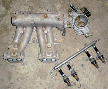
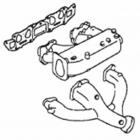
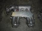
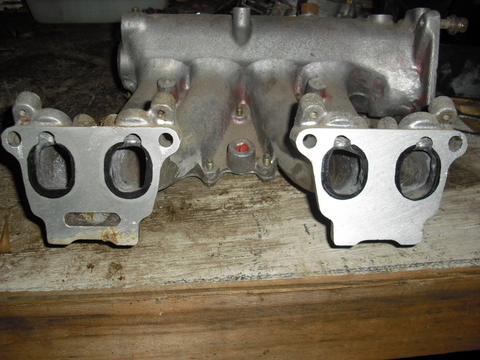
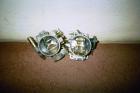
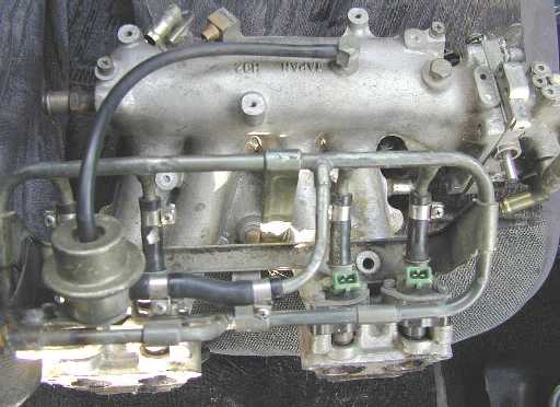
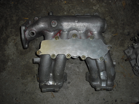
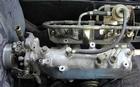
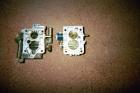
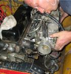
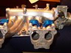
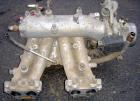
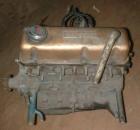
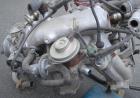
 A14 EFI manifold
SSS as I remember at one stage they had import carbie A15 engines for round $600 and injected A14 and A15 for around $800
Reportedly, Nepean Sports classics in Castlereagh NSW was selling import motors. carlos' son ran one. These are fairly sought after by the rally guys as the narrow runners provide torque and the length also good top end, too small for a big A15 though.
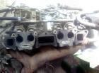
These possibly came in later model Nissan Vanettes, the reason they seem rare is both my manifolds broke across the bottom of no's 1 & 2 inlet runner. Plus it suffers from reversion with a big cam.
These were also available in asian markets (Japan, Singapore, etc).
quote:
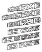
- A14 EGI = HB310 (1978-1980) Type-GX & SGX
- A15 EGI = PB310 (1980-1981) Type-GX & SGX
As for the name in Japan, Nissan calls EGI and Toyota EFI.
Although the EGI system should excel Carburettors in the performance, old EGI is inferior to Carburettors.
Discussions:
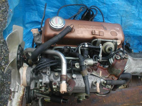
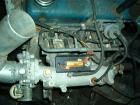
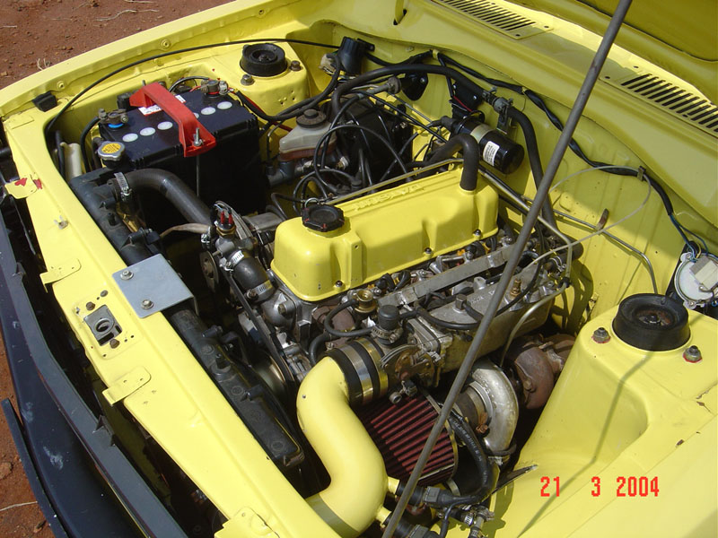
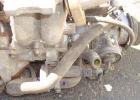
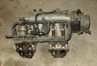
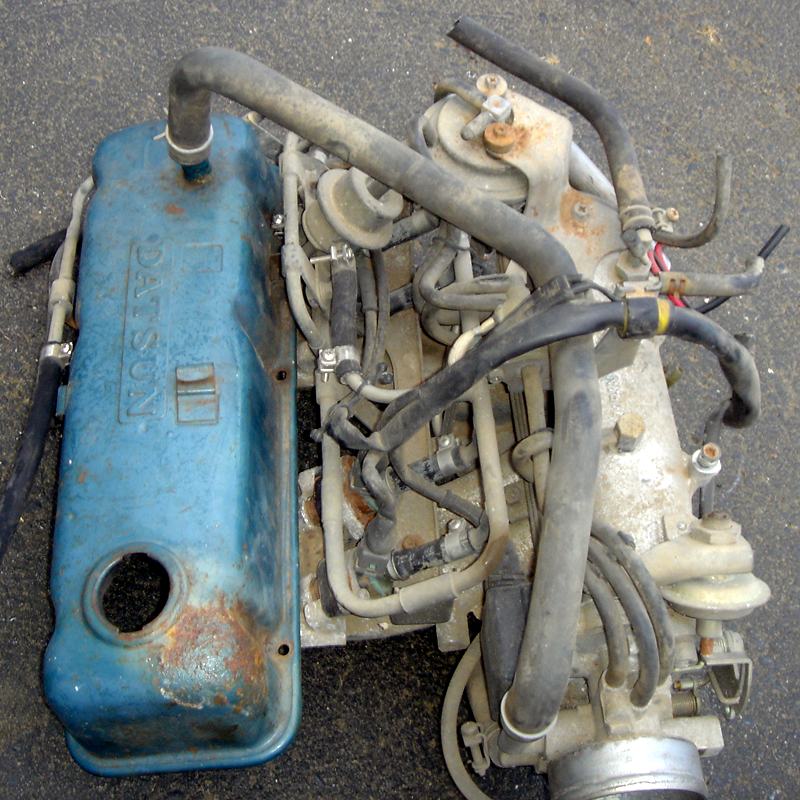
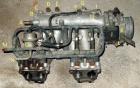
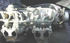
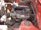
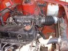
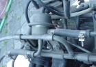
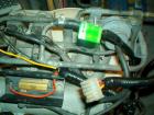
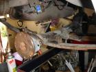
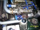
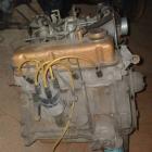
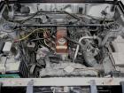
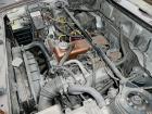
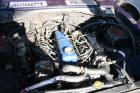
B310 factory setup (less air intake tube):
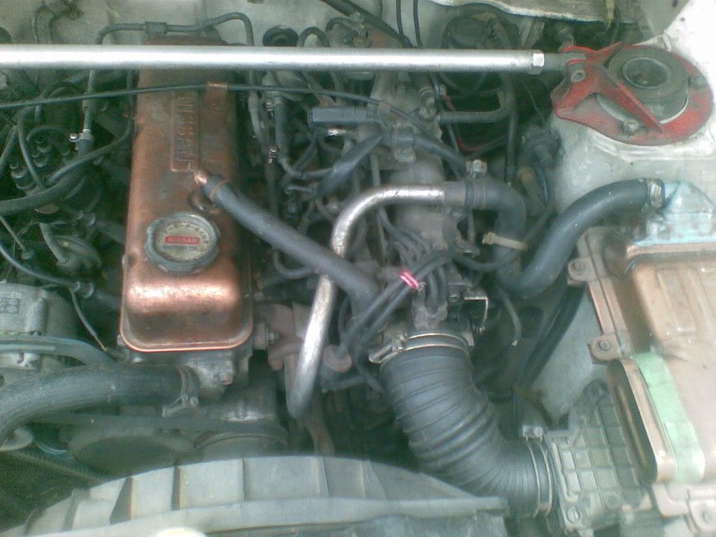
- This car is missing the air induction piping that goes across the radiator (see 200SX EFI for layout and diagrams)
- As you can see here, the setup is nearly identical to 1980 200SX EFI system.
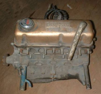
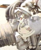
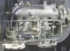
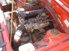
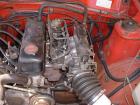
B310 Engine

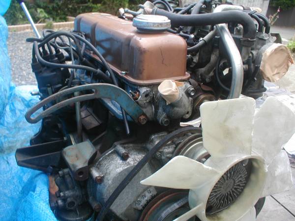
B310 Factory Setup
Performance
This factory Nissan setup was designed for typical mass-market street performance. Expect better low-speed horsepower performance than a stock DCH306 carburetor (due to the longer runners), AND increased peak horsepower.
Quite a large horsepower difference:
- A14E: 92 PS @ 6400 rpm, 11.7 kg-m @ 3600 rpm
- A14: 80 PS @ 6000 rpm, 10.2 kg-m @ 3600 rpm
1980/11/28ドアセダン1500 SGX-E エンジン: A15E型 最高出力 PS/rpm: 92/6000 最大トルク Kgm/rpm: 12.3/3600クーペ1400 RS-E 形式 A14E型 最高出力 PS/rpm 92/6400 最大トルク Kgm/rpm 11.7/3600http://nms.nissan.co.jp/contents/product/SUNNY/spec/04/04_112.html
However, it is not a racing system. In a heavily modified engine, carburetion has more potential:
Quote
A factory EFI setup imported from Japan was tried, and found to be much smoother, but ... restrictive above 6000rpm when used with the [racing] cam.
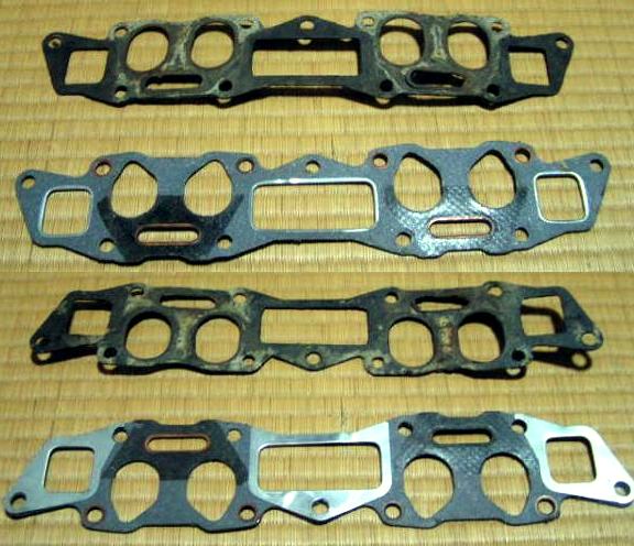
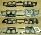
Manifolds
- 14035-H9201 GASKET-MANIFOLD TO CYLINDER HEAD A14E, A15E
- has notches at the top for the injectors
You can use a standard A14 wet gasket (for manifold with water ports) and notch it.
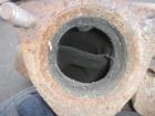
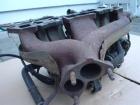
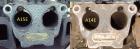
Exhaust
The exhaust manifolds have not heat riser valve, and do not fasten to the bottom of the intake manifold -- like the A12GX manifold.
A14E has a free-flowing single outlet exhaust manifold:
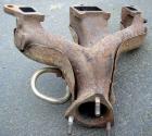
Certain other late model A-series engines are similar, but the A14E manifold is unique.
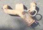
A15E has a twin-outlet exhaust which looks nearly identical to A12GX Engine

- 14004-H9200 MANIFOLD-EXHAUST A14E
- Single outlet (A14-style, uses regular A14 Exhaust piping)
- 1.5 exhaust. The inner portion is about 1-5/8 max diameter
-
- dual-plane design
- Single outlet (A14-style, uses regular A14 Exhaust piping)
- 14004-H9260 MANIFOLD-EXHAUST A15E
- Dual outlet (A12GX-style)
- 20711-H9200 GASKET-EXHAUST
- 20020-H9200 TUBE ASSY-EXHAUST FRONT [to convertor] NICHIRA A15E F5
- 20020-H9210 TUBE ASSY-EXHAUST FRONT [to convertor] NICHIRA A15E F4
- 20602-P6700 NUT [for pipe to manifold] (3) $4.53 USD
- replaced 20602-F1700 NUT
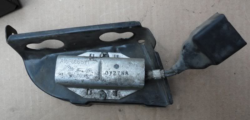
The sheet-metal cover over the manifold:
- 16590-H9201 COVER ASSY-EXHAUST MANIFOLD A14E
- 16590-H9260 COVER ASSY-EXHAUST MANIFOLD A15E
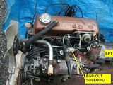
The tube is for EGR, and bolts to the bottom of the intake manifold
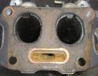
Intake

Port size
- 28x32 mm (medium oval) with injection cutout of extending up to 40mm
- compare to standard A14: 28x34
-
- Port sizes on the same manifold vary a bit

- 14003-H9200 MANIFOLD-INTAKE A14E
- 14003-H9254 MANIFOLD-INTAKE A15E
- 08223-84510 STUD $1.15 USD
- 08223-84010 STUD $0.78 USD

Be sure to port match, as ports can vary.
Black shows the gasket opening.
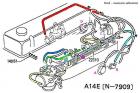
On the bottom of the intake manifold is the water hose. It connects to the front block water tube.
Water hose is "E" in this photo
- 14052-H9200 HOSE-WATER
- 08723-12000 CLAMP (2)
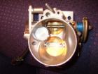
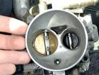
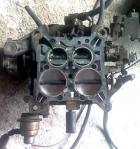
Throttle Body

- 16118-H9200 CHAMBER ASSY-THROTTLE A14E -7909 (to Sep. 1979)
- 16118-H9201 CHAMBER ASSY-THROTTLE A14E 7909- (from 9 1979)
- 16118-H9260 CHAMBER ASSY-THROTTLE A15E
- 16122-N1400 BOLT-CHAMBER A14E (4)
- 08915-13800 WASHER (4)
- 16175-H9200 GASKET-THROTTLE RETURN [Throttle body]
- 22620-W7060 SENSOR ASSY-ACCELE [throttle angle sensor]
- 08310-40814 SCREW (2)
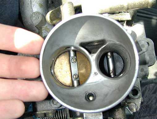
Much larger than stock, a CA20 throttle body will bolt on:
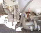
On bottom of throttle body:
- 16484-H9200 VALVE-SERVO
- 22156-85056 WASHER-SPRING
- 16485-U9800 SCREW
- 16599-N3600 CAP-CONNECTOR
- 16160-H9200 SPRING-THROTTLE RETURN
- 16182-H7820 DASHPOT ASSY TO 8004
- 16258-H9200 BRACKET-DASHPOT
- 16376-H9200 BRACKET-ACCEL CABLE
- 08360-61214 SCREW
Idle Air Bypass
Nissan calls this the Air Regulator. It adjusts the idle speed.

- 22660-H9205 REGULATOR-AIR ASSY
- 08710-61622 BOLT (2)
- 14060-H9200 HOSE-3 WAY CONNECTOR TO AIR REGULATOR
- 16439-N4202 CLAMP-HOSE
- 08723-12000 CLAMP
- 14061-H9200 HOSE-AIR REGULATOR TO CONNECTOR
- 16439-N4202 CLAMP-HOSE
- 08723-12000 CLAMP
- 14875-A7700 CONNECTOR-VACUUM HOSE
Injectors
The dropping resistor is located in the left hood ledge area forward of the strut of the B310.
- 22698-N4202 RESISTOR-DROPPING -0780 $60.65 USD
-
- 22698-W1401, 22698-D0300 RESISTOR-DROPPING 0880-
- 01451-00171 SCREW (2)
Injector Assembly
- 16603-N7616 INJECTOR $133.33 USD
- includes:
- 16449-Y8000 HOSE-INJECTOR L=53 -7909 $14.23 USD
- 16604-N7615 HOSE-INJECTOR 7910- $14.82 USD
- 16439-53A00 CLAMP-HOSE $2.38 USD
- replaced 16439-N4710
- Replaced:
- 16603-Y8005 INJECTOR ASSY -7804 L=53
- 16603-N7600 INJECTOR ASSY 7805-7909 JECS L=51
- 16603-N7610 INJECTOR ASSY 7910- DKC L=51
- 16603-N7660 INJECTOR ASSY 7910- BOSCH L=51
- 16603-V0100 INJECTOR ASSY 7910- JECS L=51
- includes:
- 16612-N8500 HOLDER-INJECTOR [lower] 7910- $6.33 USD
- replaced 16612-N4200 HOLDER-INJECTOR -7909
- 16610-N1400 HOLDER-INJECTOR U $7.22 USD
- 08310-53012 SCREW
- 08915-13510 WASHER
- 16635-N1400 RUBBER-INSULATOR INJECTOR $2.22 USD
- 16636-N1400 RUBBER-INSULATOR INJECTOR $2.22 USD
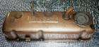
Block Ventilation
The crankcase is ventilated on top by a breather hose from the rocker cover to the fitting on the throttle body.
The rocker cover connects to the top fitting on the throttle body.
- 13264-H9200 COVER ASSY-VALVE ROCKER -7909
- 13264-H9201 COVER ASSY-VALVE ROCKER 7910-
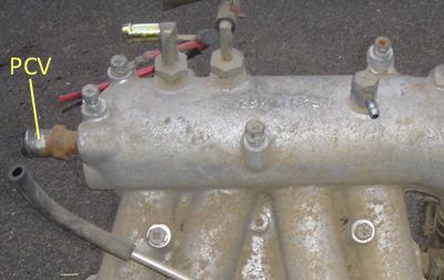
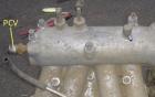
The PCV bolts to the back end of the plenum, and connects by hose down to the normal block breather tube.
Sensors
Sensors for the ECU in the factory configuration include:
* Throttle Position Sensor
* Coolant temperature
* Intake air temperature
* Oxygen sensor from July 1981. Earlier B310s did not have a lambda sensor
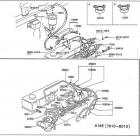
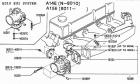
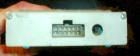
Throttle Position Sensor: Black box bolts to side of throttle body. Also called TPS (throttle angle sensor). Nissan calls this the Accelerator Sensor
#22620 in this diagram


Coolant temperature. Nissan calls this the Temperature Sensor
#B in this diagram, on bottom of intake manifold

Intake air temperature (IAT) is located in the flow meter
Flow meter at extreme bottom right
Temperature Gauge sensor is the standard type. It is not used by the factory ECU.

Oil pressure sensor is the standard one to operate the gauge light. It is not connected to the ECU. However, it is connected to the fuel pump relay (see Fuel Pump section below).
Switches
These switches are part of the EGR system (see EGR section below) and have no connection to the EGI inputs.
Nissan calls this the Water Temperature Switch.
#A in this diagram
Nissan calls this the Thermal Vacuum Valve
#C in this diagram
ECU Control
The ECU is located in the left kick panel area of the B310.
- 22611-H9202 UNIT ASSY-CONTROL A14E
- superceded 22611-H9201
- 22611-H9265 UNIT ASSY-CONTROL A15E
The air cleaner and flow meter is bolted to the left front corner in the B310.
- 16578-H9200 HOSE ASSY-AIR DUCT [from flow meter to throttle body]
- 08723-19000 CLAMP
- 08723-17300 CLAMP
- 22680-H9200 METER ASSY-AIR FLOW
- 08363-62038 BOLT (4) [fixing air cleaner L-section to flow meter]
- 22682-H9200 BRACKET-AIR FLOW METER
- 08363-61238 BOLT
- 08360-81414 BOLT
Air Duct
- 62860-H9201 DUCT AIR [goes across radiator, above the engine fan]
Air Cleaner
- 16500-H9200 CLEANER ASSY-AIR
- 16546-N4210 Filter Air $9.58 USD
- replaced 16546-N4200 ELEMENT ASSY
- 16536-N4201 PACKING [air cleaner housing gasket] $13.10 USD
- 16516-N4200 BOLT-CENTER [wing nut] [fixing top cover]
- 08363-61638 BOLT [fixing bottom pan]
- air induce valve
- 14856-H9200 VALVE ASSY-RELIEF WITH CASE
- includes 14845-N8000 VALVE ASSY-AIR INDUCE
- 16597-G2100 FILTER ASSY [for air induction valve] $12.12 USD
- 14856-H9200 VALVE ASSY-RELIEF WITH CASE
- 08363-61638 BOLT (2) [fixing L-section to fender]
- 16558-N6910 GASKET [fixing air cleaner bottom to L-section] $3.55 USD
- 08310-51614 BOLT (10)
Fuel Piping
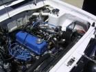
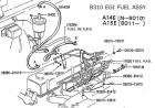
The factory fuel-rail is a brazed ring. The top of the ring supplies the injectors. Fuel enters the bottom center of the ring.
Fuel outlet is from a Pressure Regulator bolted to the ring. It is attached to intake vacuum, and lets a more or less fuel back to the oulet pipe.
This photo shows a simplied vacuum connection to the Regulator.
- 17520-H9203 TUBE ASSY-FUEL
- 08360-81412 BOLT (2)
- 08915-13810 WASHER (2)
- 16443-N7615 HOSE FUEL L=85
- 16440-U8715 TUBE-FUEL RETURN
- M: Fuel inlet
- N: Fuel outlet
- O: 22660-N4700 REGULATOR ASSY-PRESSURE [fuel]
- 16443-N4710 HOSE-FUEL (2)
- 16439-N4710 CLAMP-HOSE (4)
- 02141-31700 TUBE-VACUUM PRESSURE REGULATOR -7909 L=31 S/# B2318-73002
- 22323-W7504 TUBE-VACUUM PRESSURE REGULATOR 7910- L=170 S/# B2320-Y4000
- 01552-00481 CLAMP-EGI HARNESS A15E
- 24220-89985 CLAMP-EGI HARNESS A14E -7909
- 22472-M7000 CLAMP-EGI HARNESS A14E 7910-
- 16443-N4710 HOSE-FUEL (2)
Fuel Pump
- 17011-P7211 PUMP ASSY-FUEL $286.12 USD
- replaced 17011-N4205 PUMP ASSY-FUEL A15E
- replaced 17011-Y8000 PUMP ASSY-FUEL A14E
- 17012-F2001 BRACKET-FUEL PUMP $25.70 USD
- 22675-N4205 Damper Diaphram $110.53 USD
- replaced 22675-N4200 DAMPER-FUEL
- 22676-H9200 BRACKET-FUEL DAMPER
- 16420-E0100 SPACER-FUEL PUMP [blank-off plate] $16.10 USD
- 00915-13610 WASHER (2)
- 08120-61210 BOLT (2)
- 16400-Q0800 STRAINER ASSY-FUEL [fuel filter] $15.38 USD
- 16419-H9200 BRACKET ASSY-FUEL STRAINER
- 01461-00061 SCREW
- 16419-H9200 BRACKET ASSY-FUEL STRAINER
EGR
EGR passage is a large area on the bottom side of the inlet runners.
- 14711-H9200 PASSAGE-EGR -0709 [not shown in photo above]
- 14711-H9201 PASSAGE-EGR 7910- [not shown in photo above]
- 14720-H9200 GASKET-EGR PASSAGE
- 08110-61262 BOLT
- 08120-61662 BOLT
- 08915-43610 WASHER
- 08915-13610 WASHER-LOCK
- 08911-10610 NUT

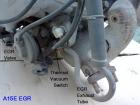
fitting into passage:
- A front:
- 14890-U7800 VALVE-THERMAL VACUUM A15E 8011- $22.90 USD
- 22120-H8900 SWITCH-TEMPERATURE WATER A14E -8010 $73.67 USD
- 22636-N4200 GASKET-WATER TEMPERATURE $1.07 USD
- B rear upper:
- 22630-N4200 SENSOR ASSY-TEMPERATURE $29.10 USD
- C rear lower:
- 14890-U7800 VALVE-THERMAL VACUUM A15E 8011-
- EGR VALVE
- 14710-M5961 VALVE ASSY-EGR CONTROL A143 -7909
- 14710-M7300 VALVE ASSY-EGR CONTROL A14E 7910-8010
- 14710-M7301 VALVE ASSY-EGR CONTROL A15E
- 14719-N3301 GASKET-EGR CUT VALVE
The exhaust manifold has the EGR tube:

- 14710-H9200 TUBE ASSY-EGR A14E -7812
- 14710-H9201 TUBE ASSY-EGR A14E 7901-
- 14710-H9260 TUBE ASSY-EGR A15E
- 14875-M2260 CONNECTOR-VACUUM STRAIGHT [fits in EGR passage, and connect to the tube]
EAI - stainless pipe at front (right side of photo)
- 14821-H9200 PIPE ASSY-EAI A14E -7909
- 14821-H9201 PIPE ASSY-EAI A14E 7910-
- 14861-H9200 HOSE AIR [connects to stainless pipe]
- 08723-13200 CLAMP (2)
- 14824-H9200 BRACKET ASSY-EAI PIPE -7909
- 14824-H9201 BRACKET ASSY-EAI PIPE 7910-
- 08360-61414 SCREW
- 14861-H9200 HOSE AIR [connects to stainless pipe]
- 14821-H9201 PIPE ASSY-EAI A15E
- 14824-H9201 BRACKET ASSY-EAI PIPE
VVT
VVT was used on A15E. Venturi Vacuum Transducer (V.V.T.) modifies the EGR vacuum signal. The VVT Valve takes venturi vacuum and exhaust manifold back pressure, and outputs the EGR signal. This systems has finer control over the EGR than earlier systems.
An on/off vacuum switch has an input of intake vacuum, and activates on the high vacuum during deceleration. The output is used cut to power to the vacuum switch valve.
2-port thermal vacuum valve closes when the engine is cold, so no vacuum can flow to the EGR valve.
14771-H9215 VALVE ASSY-VVT
* 14755-H9200 TUBE-PASSAGE TO BPT L=110 S/#B2318-N3300 [small rubber hose]
** BPT = Back Pressure Transducer?
* 14750-H9201 TUBE ASSY-VVT CONTROL [small metal connector to exhaust]
14956-H7206 VALVE ASSY-SOLENOID EGR CUT A15E
14957-H7200 BRACKET-VACUUM SWITCH -7911
14775-H9201 BRACKET-VVT VALVE -7909
14775-H9202 BRACKET-VVT VALVE 7910-7911
14775-H9203 BRACKET-VVT VALVE 7912- [large bracket]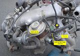


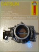
Service Manual
Fuel Pump
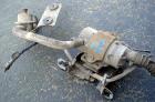
The nice thing about the factory system is that it uses an external fuel pump. This fits below the fuel tank in the B310, 280ZX or 200SX.
- 43-64 psi Cut-off discharge pressure
- 5.1 amps Design current, so use a relay (see wiring section)
280ZX pump and damper
Fuel pressure (after fuel filter)
- 30 psi at idle
- 37 psi at Initial full throttle
Since the 1200 fuel tank is baffled only for carburetor, you might wish to fit a anti-swirl pot under the bonnet. Run a low pressure fuel pump to it. And the EFI pump from the pot to the filter & fuel rail. If you get a float-style pot you wouldn't even need to fit a return line to the 1200 tank.
Check valve fits between tank and pump.
High-flow fuel filter is under the bonnet.
- 16400-00004 Fuel filter 280ZX $12.08 USD
Wiring
Wiring here is based on USDM 1981 200SX (Silvia).
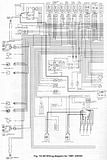
The simplified "4-wire" setup, which assumes you are using a factory wiring harness cut out of a donor car, is:
- IGN
- START
- GROUND/EARTH
- FUEL PUMP
Engine Harness

Engine harness
- Injectors
- Air Regulator (air bypass system -- for idle speed)
- EGR/VVT vacuum-cut switch (can be disconnected)
- Throttle Sensor (Throttle position sensor)
ECU
- 22612-N7801 to 0681 (no O2)
- 22612-N8500 from 0781 (O2 sensor)
- Wires to passenger compartment
- EFI relay
- INPUTS
- coil negative (tach sense)
- air flow meter
- air temp sensor (in flow meter)
- throttle valve sensor
- START wire for ignition switch (to indicate when to do cold-start enrichment)
- water temp sensor (on underside of intake manifold)
- O2 sensor (not used on early B310)
- OUTPUTS
- Injector output
FUEL PUMP
- 2 wires to pump
- B - earth/ground
- LgR - (Light Green with Red stripe) pump power
- 3 relays (FUEL PUMP RELAY 1, FUEL PUMP RELAY 2, FUEL PUMP RELAY 3)
- The extra relays are for safety. Relay takes inputs from Alternator, Oil pressure switch and ECU. Pump will shut off if engine dies because Oil and Charge will go out. This is important for safety in a crash.
Dropping Resistor
Fuel injector dropping resistor: 2.35 ohms resistance. Two blue (L) wires.
EFI Relay
There is a dedicated fusible link for the ECU


- 25230-C9900, 25230-C9907 RELAY ASSY
- SWITCH:
- C: BW wire from IGN switch
- E: B ground/earth
- D SOURCE: from Brown fusible link to Light Green/white
- B OUTPUT: LgR to Red wire to ECU #207
Fuel Pump Relays
At the minumum you need one relay for the fuel pump. It draws over 5 amps, so you don't want to run it directly through the IGN switch.
Although you could use one, for safety the Datsun factory system uses a chained system of three relays.
- Nissan 5-blade relay
- 25230-C9900, 25230-C9907 RELAY-FUEL PUMP JIDECO
- 25230-C9905 RELAY-FUEL PUMP NILES
Fuel Pump Relay 1
Pump On/Off: this relay engergizes the Fuel Pump and Air Regulator, but Relay 2 can open the circuit.
- SWITCH:
- C: (Lg) from Fuel Pump Relay 2 OUTPUT (Lg)
- E: Earth/ground
- D SOURCE: BW from IGN switch
- B OUTPUT: LgR
- to Air Regulator LgR
- to Fuel Pump LgR
Fuel Pump Relay 2
Pump Power: This relay is wired NORMALLY CONNECTED (i.e. when off). It passes on to Relay 1, but when Relay 3 is on it disconnects.
- SWITCH OFF:
- C: L from ACC L FUSE 15A
- E: (switched ground) LW from Relay 3 OUTPUT (LW)
- D SOURCE: BW from IGN switch
- A OUTPUT NORMALLY CONNECTED: Lg to Relay 1 SWITCH(Lg)
Fuel Pump Relay 3
Pump Cutout: This disconnects the Pump Feed relay in certain scenarios.
SWITCH:
* C: BW from IGN switch
* E: WR to DIODE to Alternator WR
D SOURCE: YW to GROUND/EARTH via Oil Pressure Switch
B OUTPUT: LW to Relay 2 SWITCH (LW)
200SX Oil Pressure Switch is a dual-wire type because 200SX has an oil pressure gauge, but we only needs a regular sensor used on all A-series engines.
25070-80W0 DUAL OUPUT
* On/off pressure switch for OIL light & fuel pump relay
* Resistor sensor for gauge
Photo Index


 more like this