User Login    
 + Register
  • Main navigation
Login
Username:

Password:


Lost Password?

Register now!
Fast Search
Slow Search
Google Ad


Main : Misc Tacho wiring diagram

[<   Previous  6619  6620  6621  6622  6623  6624  6625  Next   >]

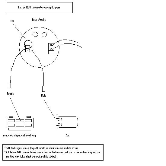
Tacho wiring diagram
Tacho wiring diagramPopular
SubmitterWattageMore Photos from Wattage   Last Update2003/12/9 21:50    Tell a friendTell a friend
Hits10897  Comments12    0.00 (0 votes)0.00 (0 votes)
Pretty straight forward....you should have the wires already in your loom (but taped up), if not, run some new ones

[<   Previous  6619  6620  6621  6622  6623  6624  6625  Next   >]

The comments are owned by the poster. We aren't responsible for their content.

Poster Thread
kululadotgroen
Posted: 2007/8/29 20:08  Updated: 2007/8/29 20:08
No life (a.k.a. DattoMaster)
Joined: 2006/7/12
From: Cape Town ZA
Posts: 1054
 Re: Tacho wiring diagram
Sorry for digging this old piccy up, but I have my 1200 tacho working with the 4AGZE and aftermarket management. This is no great feat, as can be seen and read from the piccy and comments, but what might be interesting is what happened when I sorted out my wiring loom. I had the whole thing laid out on the garage floor, connected up to a 12v power supply. The tacho would show 2000 rpm when the other two wires were plugged in, remember the coil couldn't be working at his point. If you unplugged it it would fall back to 0, this just shows how little of an inductance it needs to pick up a signal...

Poster Thread
Wattage
Posted: 2003/12/10 5:12  Updated: 2003/12/10 5:12
Home away from home
Joined: 2002/11/13
From: Portland, Vic
Posts: 221
 Re: Tacho wiring diagram
The male and female labels are pretty much only there to show what goes where.....not sure if they can (or should be!) swapped.

Poster Thread
Buff
Posted: 2003/12/10 5:56  Updated: 2003/12/10 5:56
Home away from home
Joined: 2002/11/30
From: Tas
Posts: 365
 Re: Tacho wiring diagram
Nice diagram - by the way thanks for the pedal it turned up the other day - much appreciated

Poster Thread
UTE18L
Posted: 2004/3/15 5:25  Updated: 2004/3/15 5:25
Home away from home
Joined: 2003/9/1
From: Sydney, Australia
Posts: 689
 Re: Tacho wiring diagram
Can i still hook up the coupe tacho if ive got a CA18DE.

What will i have to do different to whats in this diagram?
seeing i dont have an A-Series wiring loom

Cheers Henry

Poster Thread
dattodevil
Posted: 2004/5/11 7:41  Updated: 2004/5/11 7:41
No life (a.k.a. DattoMaster)
Joined: 2004/1/20
From: Christchurch. NZ
Posts: 1382
 Re: Tacho wiring diagram
Now, without trying to offend anyone, I believe that the wiring Diagram is incorrect, you wont get a pulse signal (which is required for a Tacho to work) from the + side of the coil. All tachos are wired on the negative side. Hence the White/Black wire. the tacho is wired in series on the 1200, if you wire it in parallel the car wont start, because that will just earth the points (effectively how a kill switch works) Hope this helps.

Poster Thread
phunkdoktaspok
Posted: 2004/5/11 9:25  Updated: 2004/5/11 9:25
No life (a.k.a. DattoMaster)
Joined: 2002/9/23
From:
Posts: 2809
 Re: Tacho wiring diagram
Dattodevil without trying to offend, you are actually incorrect.
Not all tachos are wired to the negative side of the coil.
Datsun tachos work off induction. ( basically magnetism )
As in the diagram there is no actual physical connection of the tacho to the coil.
The positive supply to the coil is looped through the tacho. As the coil creates sparks, the coil is charging and discharging, this is shown in the current running to the coil through the positive wire as going high then low. This create a strong magnetic field and then a low magnetic field. This magnetism induces a pulse into the tacho to make it operate.
I dont know how to explain it any simpler. Hope this helps you understand, if not let me know.

Poster Thread
dattodevil
Posted: 2004/5/11 11:54  Updated: 2004/5/11 11:54
No life (a.k.a. DattoMaster)
Joined: 2004/1/20
From: Christchurch. NZ
Posts: 1382
 Re: Tacho wiring diagram
Currently I have my tacho wired on the negative side and it works fine, once I get my ute completed I will try it as in the diagram. If it works then well and good. I do understand that it works of induction, I just never realised that the slight current fluctuation on the + side of the coil would be enough to trigger it.

Edit: my apologies, The tacho can go either side if the coil, I had the picture of the test light running from + side and of course it will stay on because it is creating its own earth. Thanks Steve

Poster Thread
ddgonzal
Posted: 2004/5/11 20:52  Updated: 2004/5/11 20:52
Moderator
Joined: 2001/5/3
From: 48 North
Posts: 31575
 Re: Tacho wiring diagram
Good point. Since it's current flow (not voltage) it shouldn't matter which side of the coil the stock tacho is on. Just as long as it is not grounded! It's just that Nissan made it easy to wire into the + side by putting the b/w wires behind the dash.

Poster Thread
ddgonzal
Posted: 2008/7/1 7:22  Updated: 2008/7/1 7:22
Moderator
Joined: 2001/5/3
From: 48 North
Posts: 31575
 Re: Tacho wiring diagram
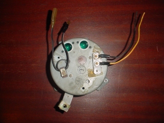
What are the two wires on the right side for?


Wiring article

Poster Thread
benny
Posted: 2008/7/1 7:32  Updated: 2008/7/1 7:32
No life (a.k.a. DattoMaster)
Joined: 2002/6/14
From: Sydney
Posts: 2598
 Re: Tacho wiring diagram
yellow with red trace [from memory on the colour of the wire] is for the +12V to energise the winding inside the tacho, so that the needle can sweep and the other is ground.

Poster Thread
ddgonzal
Posted: 2008/7/6 7:06  Updated: 2008/7/6 7:06
Moderator
Joined: 2001/5/3
From: 48 North
Posts: 31575
 Re: Tacho wiring diagram
Thanks benny, I can confirm. They are Ground/earth and IGN. My tachometer is working now.

Poster Thread
heineken
Posted: 2012/3/2 0:21  Updated: 2012/3/2 0:21
Just can't stay away
Joined: 2010/3/12
From: Manila Philippines
Posts: 118
 Re: Tacho wiring diagram
have this early tach and its not working, how can you determine if its defective or not. I followed what's on the diagram and for some reason i cant get it to work.