|
|
| Re: racetech's 1200 SR20VE Project |
Subject: Re: racetech's 1200 SR20VE Project
by racetech on 2012/11/6 8:55:12
October 2012 - Cams&Springs - Fuel Pressure Regulator
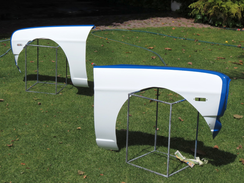
Seeing that we were still trying to get the plugs for the flares 100% correct, I at least had more than enough to keep myself busy. These flares is turning out to be the biggest reason for all my headaches and sleepless nights. After I finished with them, they were sent to the Spray painters for the final work and paint. After a week or three I got the two rear units back fresh from paint on the Friday, the Saturday morning I placed them in the sun as advised to make sure the paint hardens 100%. I left home to get some supplies and wood to reinforce the moulds I will start making the Sunday. Once I returned home with the supplies I saw that the paint on the plugs wasn't looking as good as when I left, further inspection revealed that they had some sort of sun burn, some places the body filler beneath the paint was separating from the foam etc. The paint was cracking and my heart sank to the floor. You know that feeling you get when you spend a lot of effort, money, time and patience on something just to see it break or fall apart, well I was so angry I could not even utter a swear word. I just left them and proceeded to cut the wood to the desired sizes for future use if we could save the plugs. After that I retired thinking how much money will I need to spend on import a set of flares, get a set of side shafts made and rebuilding the front and rear suspension arms. I was not in happy land.
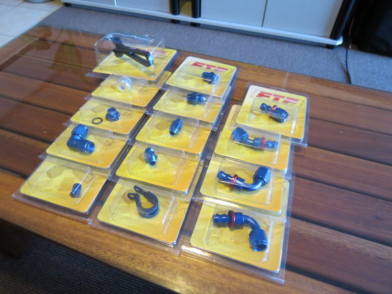
Seeing that I wasn't as positive as needed, work was slow, but at least some parts arrived and I could find comfort in and do some work on the car. The first packages came from FTF - Future Tech Fittings and Aeroquip, these contain all the relevant fittings, adaptors and hose in AN6 size needed to complete the new piping around the FPR and fuel rail. These FTF products looks like quite a decent product, I presume they are FTF branded from some other supplier. I just hope they live up to their price as they aren't exactly cheap.

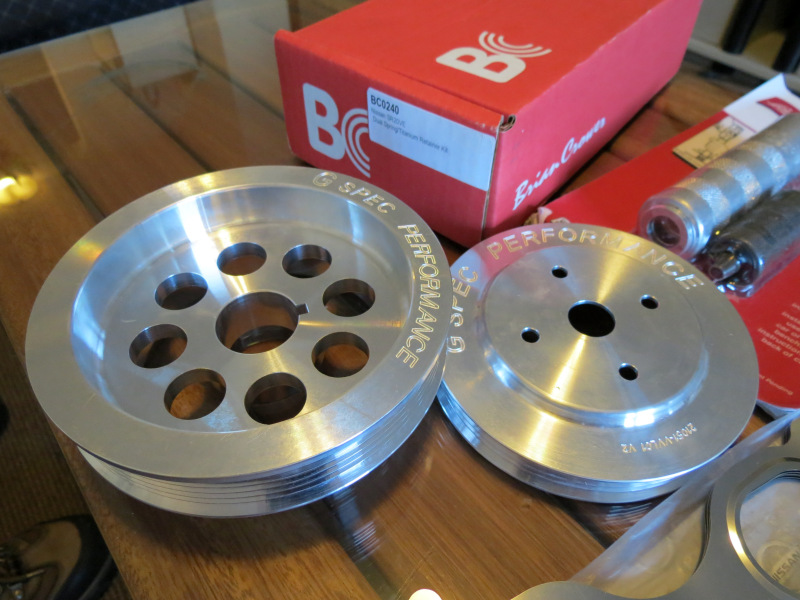
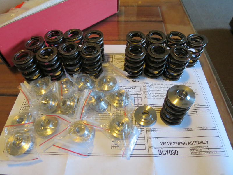
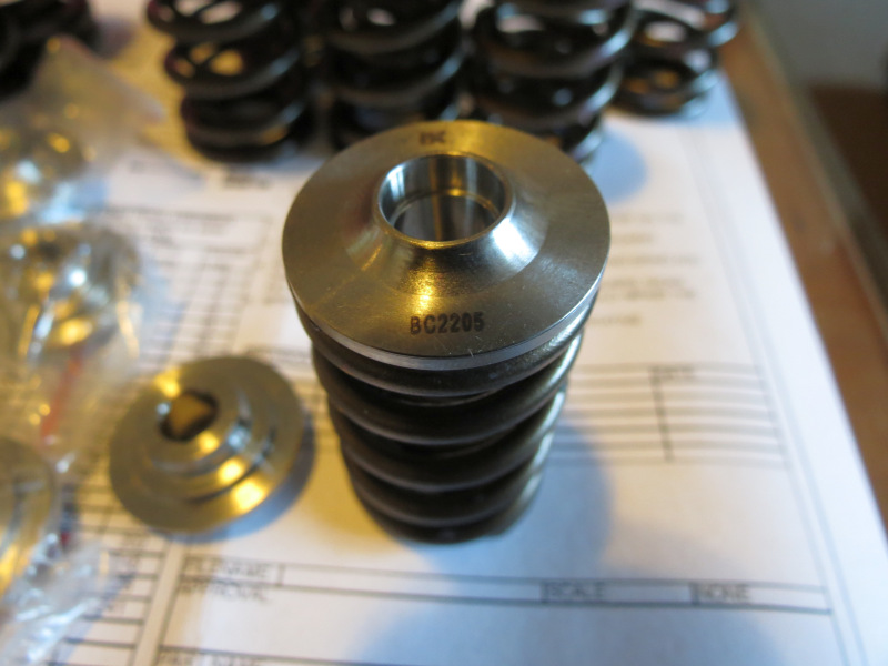
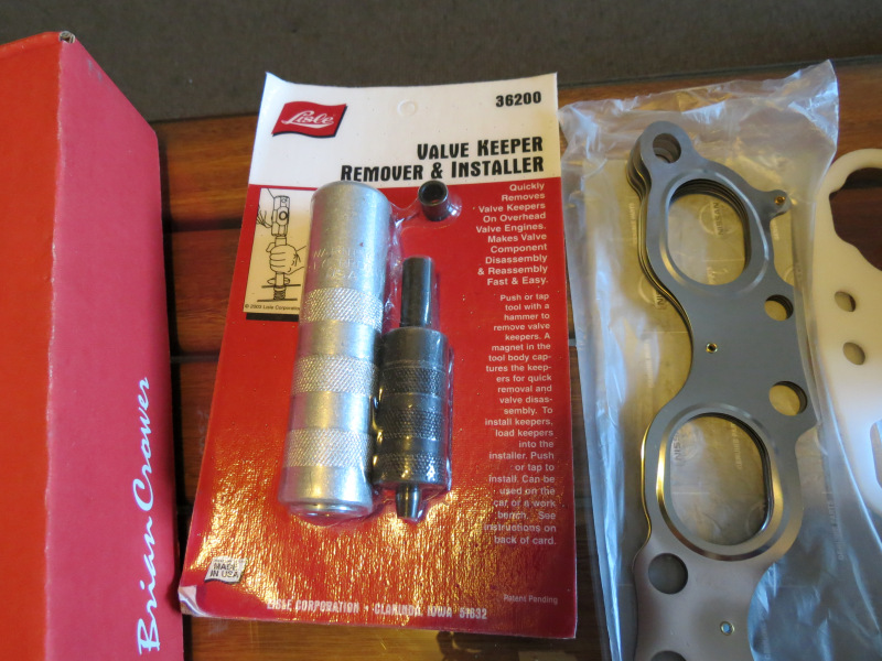
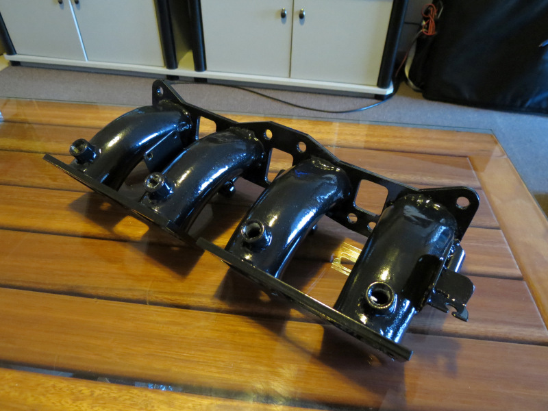
The next little box was from our friends in the States, [img]www.gspec.com" target="_blank">GSpec to be exact. I must say I had quite a pleasant experience working with them, the only thing that bothered me was the fact that I had to wait for some parts and was not told about it. All in all Greg is a very nice person to work with. Unpacking the box revealed the following parts, Genuine Nissan Front crank seal, SR20VET exhaust gasket, radiator cap and washers for the VE tappet cover. A set of Gspec vernier pulleys was included to be mated to the SR16VE N1 cams and under drive pulleys. A thermal spacer and a set of plugs was added. Then while I was busy ordering a set of [img]http://www.briancrower.com/makes/nissan/sr20det_valvetrain.shtml" target="_blank">Brian Crower Valve Springs and Titanium Retainers for the VE to be on the safe side and a Lisle Valve keeper and remover tool to make the job easier since the head will stay on the engine. On the same day the ITB's manifold also got back from Metal Seal Coatings after receiving a new layer of plating and black epoxy.
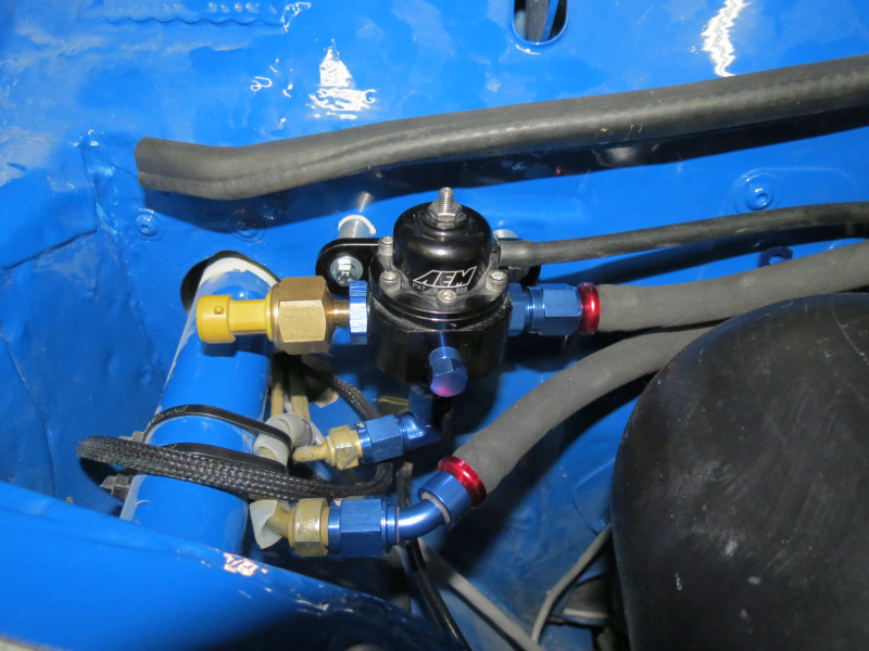
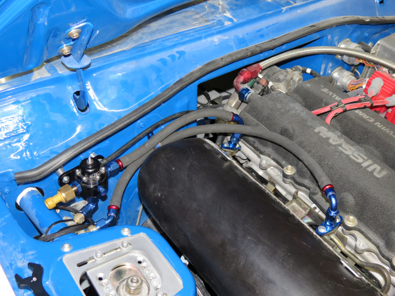

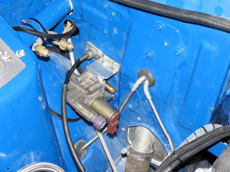
The first order of business was the Fuel Pressure Regulator, this had to be mounted and the relevant pipes made to fit the new unit. The FPR in question was the AEM unit supplied by [img]http://shop.rezlo.com/SA/index.php?act=viewProd&productId=896" target="_blank">RAW, this time round I opted to try push lock fittings and hose, seeing that I'm not a big fan of the braided lines any more, it is hard working with them, not that flexible and the look of a black pipe just looks better, thus I opted for some decent Aeroquip hose. Finding an ideal location for the unit took a while to plan, seeing that the fittings is only at a certain angles and the pressure transducer takes up quite some space, at the end of the day I opted to mount it high on the firewall to make the routing of the hoses the easiest. I had to use one of the blank off plugs for one off the intakes and tap 1/8 NPT thread to mount the pressure transducer as out of the way as possible. I would just like to share the following, whenever you need to use high quality hose for low pressure applications, consider push lock fittings and hose, especially if you will be removing it often. These hose assemblies are a breeze to put together. It will be hard not to use this on future projects or replace some of the existing hose assemblies.
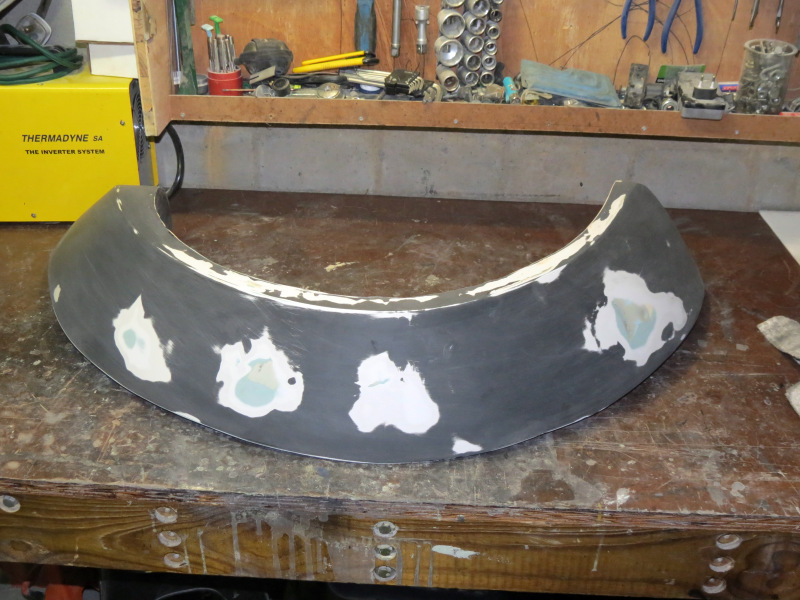
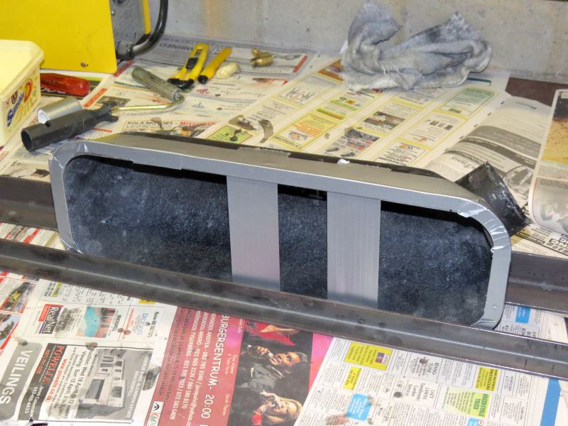
While all this was going on, my brother came up with the brilliant plan to cover the plugs for the flares with a single layer of fibreglass tissue and resin, this would create a decent strong barrier, which will keep out thinners and harmful substances that could resolve the inner foam again. The plugs was sanded again and the tissue added, hopefully this will do the job and I can get them back looking mint. I also found some time in between to glue the aluminium flange to the air box, this will be used to create a positive seal between the mounting flange and the air box.
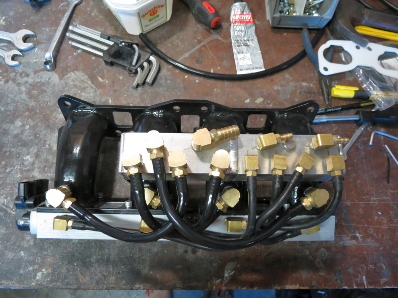

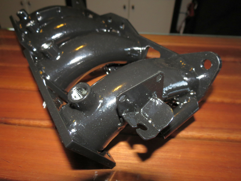
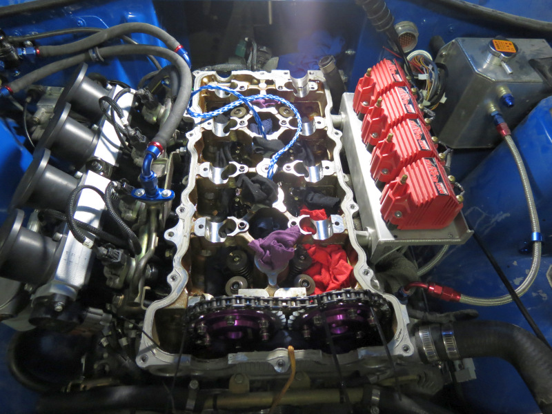
Since I had a 100% working fuel pressure regulator on the car, I wanted to start the engine with the throttles, make the necessary adjustments if needed before installing the cams. I was just afraid to many changes at once could prove to be too much for my limited mapping experience to figure out where to start if something was not working. I have struggled quite a lot with management in the past due to a lack of knowledge, I must add, this was with locally produced units, let's see if the imported units can live up to their reputation and price tag. First on the to-do list was the piping for the vacuum manifolds to work, you'll notice a welding line in the middle of the unit, this is a separator which actually holds two separate manifolds together, one for accessories needing vacuum like the MAP sensor and FPR, the other for idle control. I opted to use a pipe per cylinder on both sides, it is quite a maze of pipes, but luckily it is well hidden and cannot be seen. Seeing that it is already so busy under the intake manifold, I decided to remote mount the IACV - Intake Air Control Valve. The ITB's was installed, fuel lines fastened and during the first crank the engine started, I was amazed, this without a single change to the management besides calibration of the MAP Sensor and Throttle position sensor. Seeing that it was only a temporary install the big leak was not bothering me much, as I knew once the setup is installed permanently, hopefully the air leak will be gone.
http://www.madev.co.za/wp-content/upl ... 12/11/DattoOctober521.jpg[/img]
http://www.madev.co.za/wp-content/upl ... 12/11/DattoOctober531.jpg[/img]
Seeing that TDC is marked clearly on the Gspec crank pulley, I decided to install the under drive pulleys before the cams, this went flawless besides the 15 minutes spend on making a quick puller to get the old pulley from the crank. The biggest hiccup is in the belts, the power steering and water pump belt is a easy one in the country, the difficult one is the alternator, especially since I removed the air con. The pulleys are for a 6pk belt, but I was only able to source a 4pk unit in the correct length, I'm pretty sure this will be fine for the interim, but I will try and get the correct belts sourced or import it.
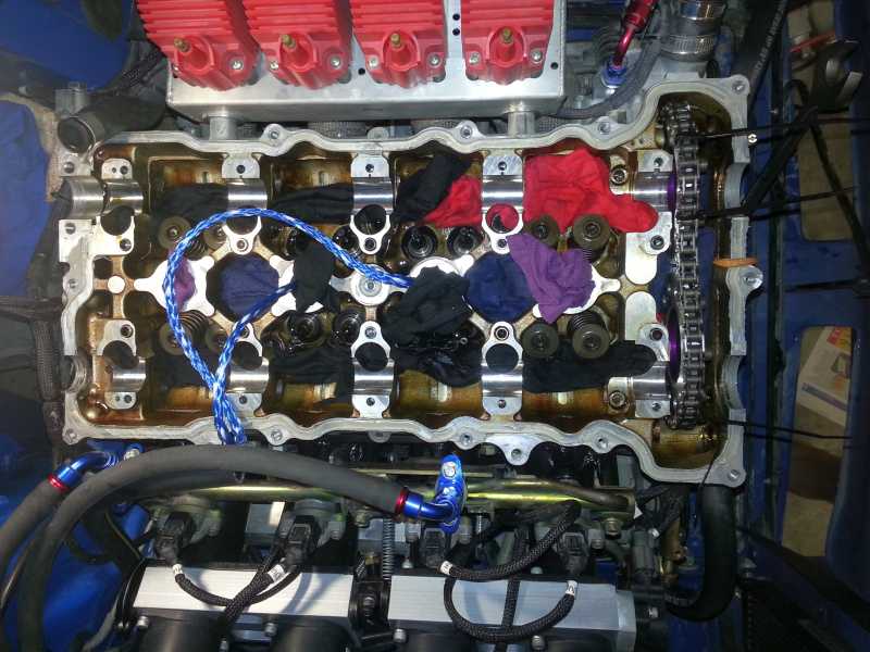
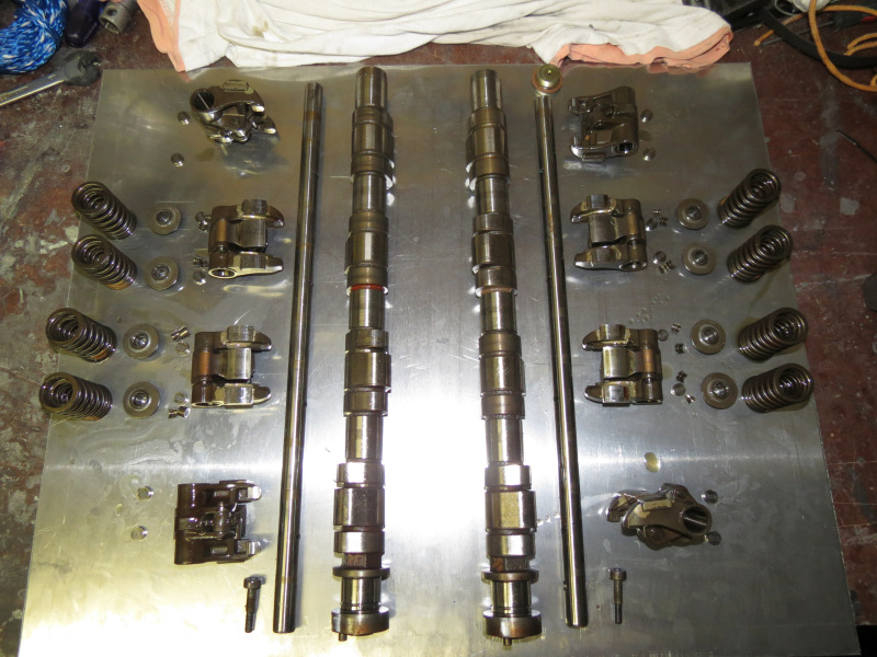
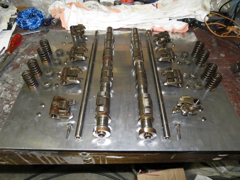
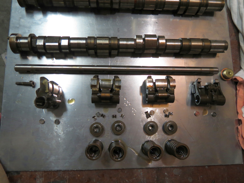
Next in line was the springs and retainers and finally the cams and verniers. For anyone trying to attempt this, use this guide [img]http://www.sr20forum.com/sr20ve-sr16ve/198451-how-install-cams-springs-retainers-ve.html" target="_blank">How to install Cams and Springs and/or Retainers in the VE, it was a great help, just a few pointers, when removing the rocker shafts a flat screw driver works nicely, put the flat piece in the hole, add some sideways pressure and pull them out. Mark the rocker shaft orientation before removing, even though the set bolt hole is off centre. Besides that, there is not a lot I can add that the guide does not cover, work as clean as possible, make sure to have enough clean rags covering all the oil return holes and between the various parts to keep the keepers retained in a certain area if the feel the need to explore. The Lisle tool works great for removing the keepers, put is quite tricky hen installing them, use a decent size hammer and make sure to align everything with the hand before whacking. I used the old rope in cylinder trick for keeping the valves in place, just make sure the holes to the plugs is clean before running the length of rope down the cylinder, for reference I was able to get about 4m of 8mm ski rope down a cylinder.
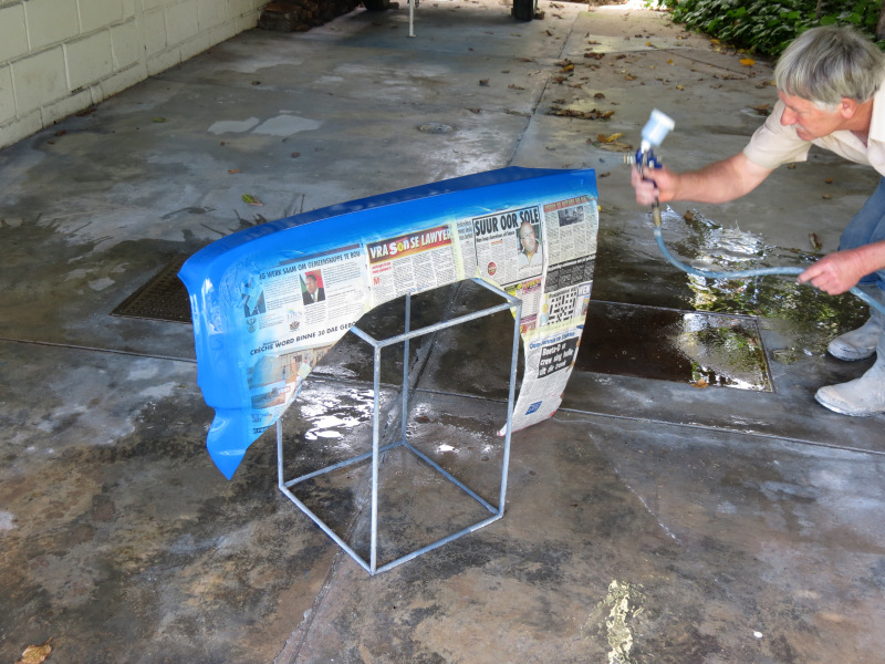
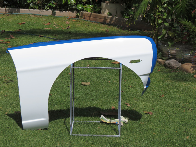
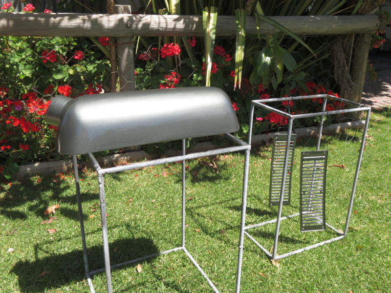
I was lucky enough to be invited to help do some work on a lattice mast just above my parents home, this provided me with the ideal opportunity to get the front fenders sprayed, while I was there I spend some time on the airbox to get it smoother and decided to spray it a dark grey metallic. It came out good, not 100% but good enough to make sure it is working.
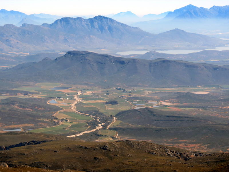
Here is a view from the mountain above my parents home and the valley where I grew up.
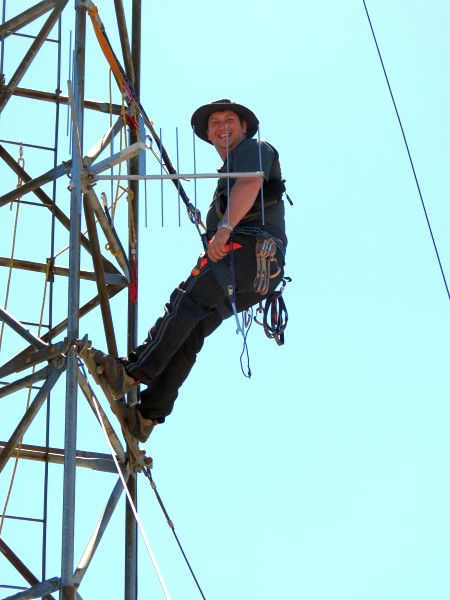
Smiling for the camera while relaxing.


A view above the clouds. This is exactly the reason why I do volunteer work, not to many people will have the opportunity in their lifes to experience this view.
|
|
;)
;)
;)
;)
;)
;)
;)
;)
;)
;)
;)
;)
;)
;)
;)
;)
;)
;)
;)
;)
;)
;)
;)
;)
;)
;)
;)
;)
;)