|
|
| Re: racetech's 1200 SR20VE Project |
Subject: Re: racetech's 1200 SR20VE Project
by racetech on 2013/6/7 14:19:34
Datto Build Fixing the List III
Having a look at the previous updates thing to still do, I actually managed to almost accomplished what I wanted to finish in the last month. The list is almost completely done, well in the next month I'm pretty sure I would be done with all the items on the list, then only the new additions will have to be sorted, but more of that later.
Without further delay, let's look how I spend my days the last month, with a sore throat as I had my tonsils removed, this can be seen as either a bad thing or a blessing as I actually had a little more time in the garage than usual, but it came at huge discomfort and pain.
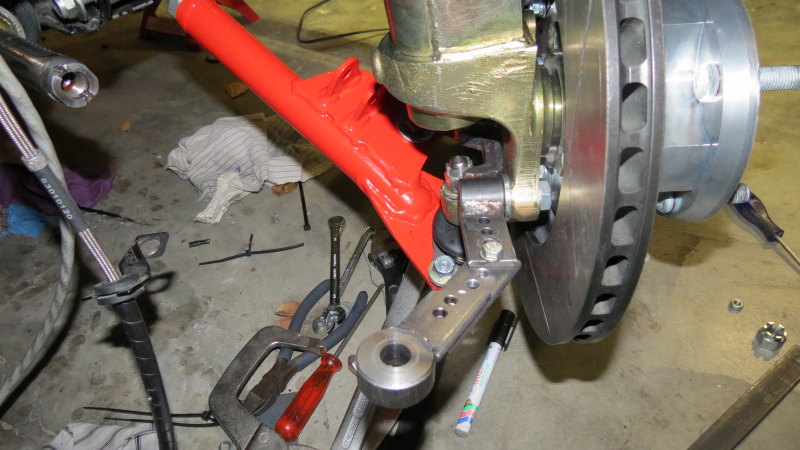
Front Struts

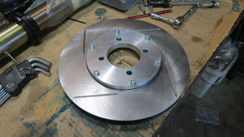
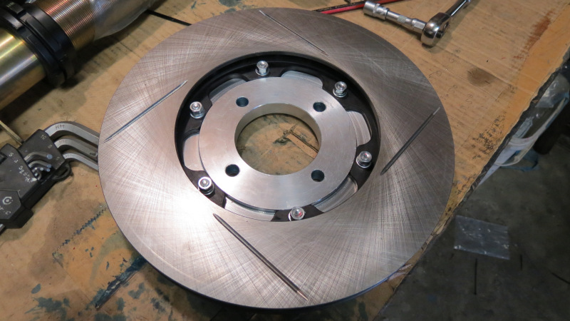


All the machining is finally done on the calliper mounting brackets, a lot of lessons were learned on these units when it comes to working with a milling machines, considering the one unit had to be remade as I had the misfortune of braking a small drill bit in one of the holes, this little bugger caused me to abandoned all hope of saving it and had to start from scratch. But as they say we learn from our mistakes.
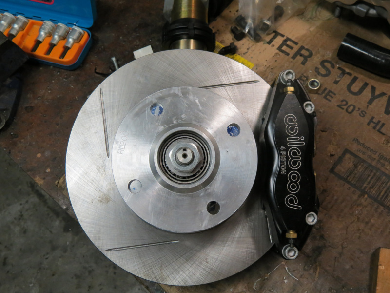


Final assembly of the rotor, hub and bells was also done, also took the time to make a quick design for the wheel speed sensors, just waiting on a piece of material and I'll make the final units. The only outstanding thing besides the wheel speed sensor bracket to make for the struts are the steering arm mounting bolts, as a normal bolt is hitting the rotor hat to hub mounting bolts, I'll have to use counter sink Allen cap to make space and the just half nuts on the other side to make double sure they will never come loose.
Front Lower Controls Arms

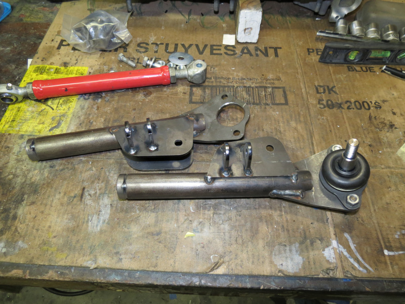
After a lot of measuring and decision making, I decided to build a set of LCA's which would be of such a length that I'm able to adjust to zero camber, seeing that I have to make some wheel PCD adaptors from 108 - 100 PCD, I can just as well mount the strut in such a way that the wheel is at zero camber on ride height with the camber/castor plates almost to the most outside adjustable position, the rest of the space between outer wheel and flare will be filled with the PCD adapters, rather all this than a setup that always have a lot of camber just to fill the empty space.

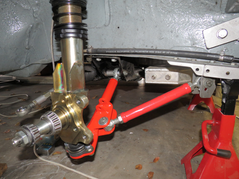

Once all this thinking was done, I just had to wait for the laser cutting and machining to arrive for the sparks to fly, once you have spent enough time to have all the measurements at hand, it's quite fast to build a set. I opted to just tack all the pieces in place, fit it and make 100% all is in order before I turned up the amps and MIG welded the pieces in place. I opted to powder coat them as my father is busy recovering from an hip replacement.
Luckily for me I was able to retain the previously made track rods, which saved a lot of work and time, just the colour that is different from the LCA's.
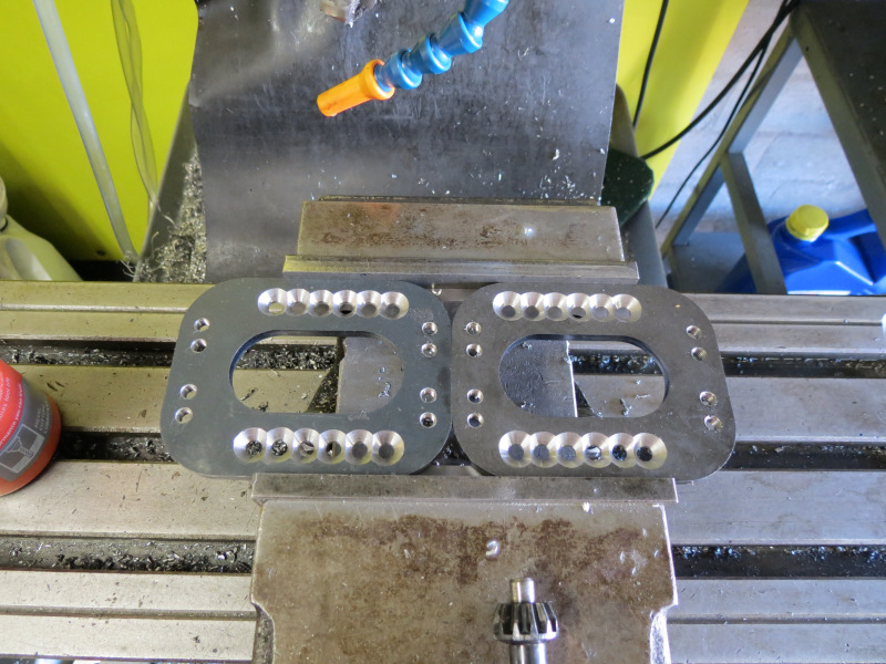
Rotary Table


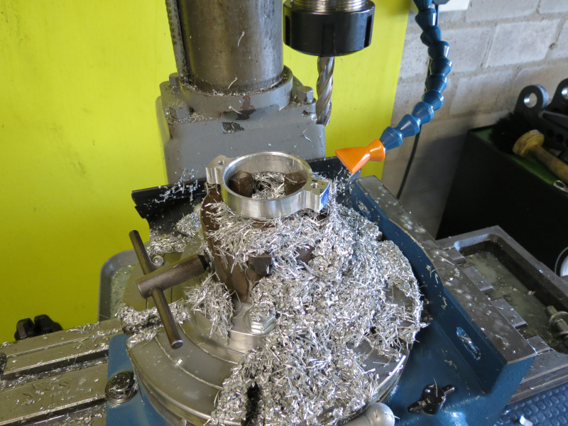
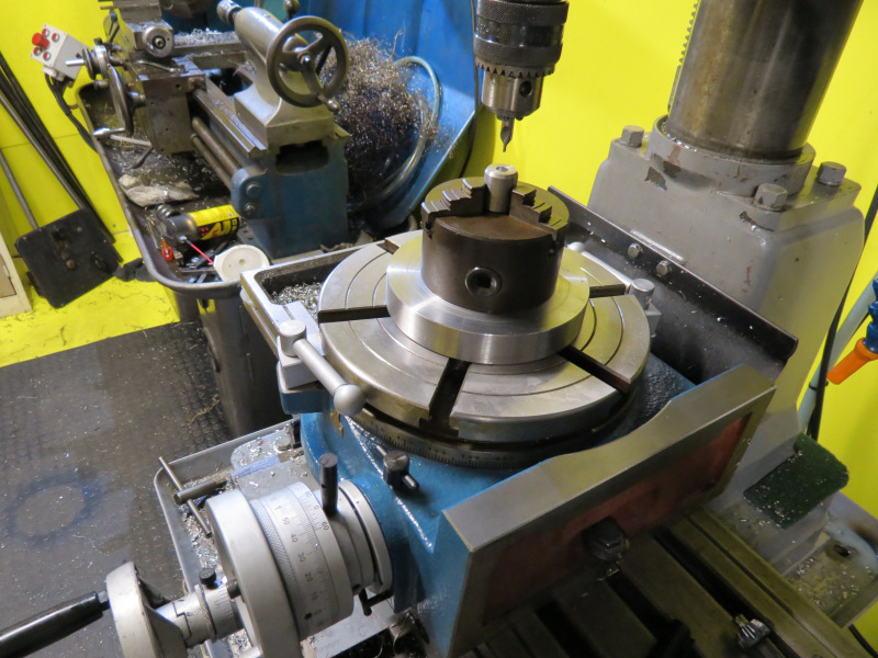
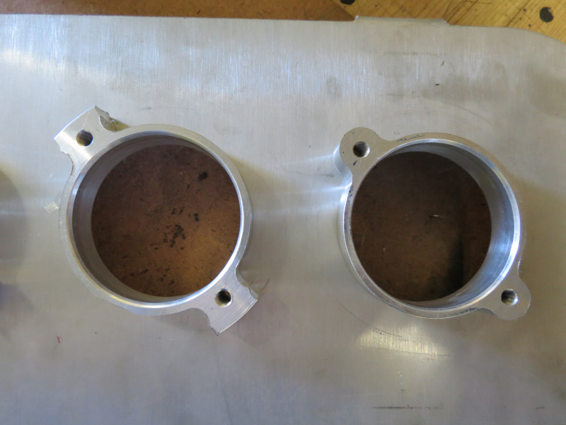


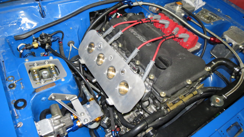
Seeing that me and my brother invested a little of our project money to buy a rotary table, I just had to think of something to use it, I decided to remove all the unnecessary material around the flanges between the ITB's and Air box back plate. The idea was good, the end results are good, but the time taken was allot. I can understand why milling work is so expensive, it takes ages and you need allot of different tools per job and these aren't exactly cheap.

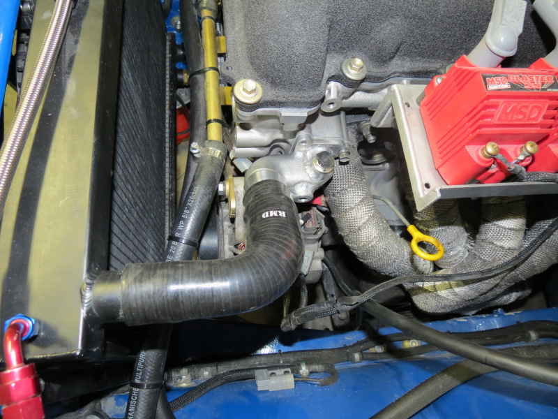

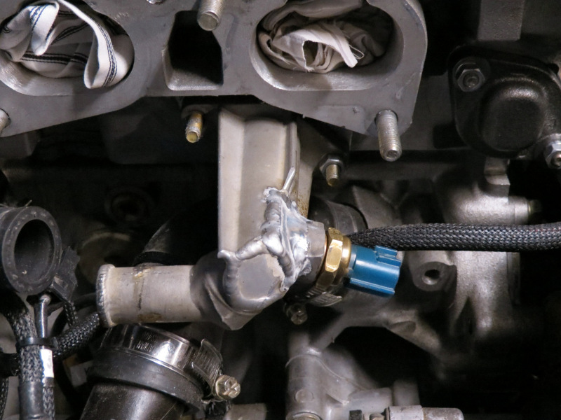
Since I had to have mounting tabs and the flanges weld, I decided to extend the water outlet on the head, to use a stock 90 degree silicone pipe that reduce from 35-32mm, now I'm finally happy with the pipe, funny how the smallest things can work on your nerves. While all of this was going on, I also moved the water temp sensor on the cold side of the head to allow the ITB's to be removed and mounted without firstly removing this unit, just a little something which could keep the tools not flying around.
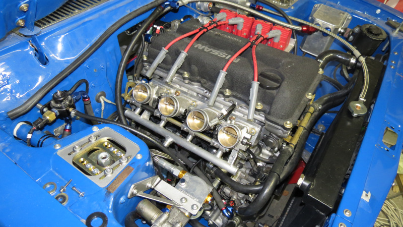
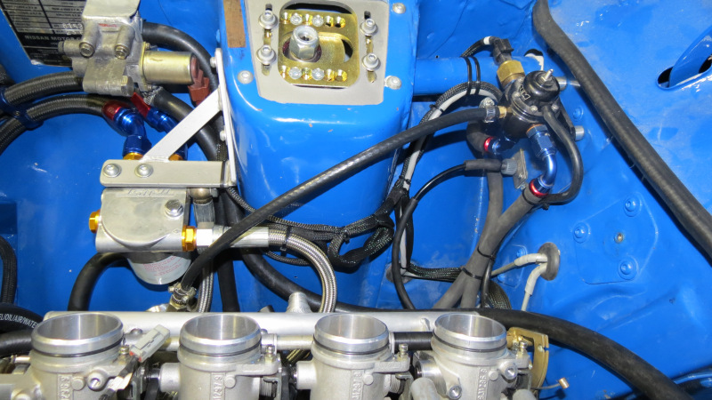
ITB's


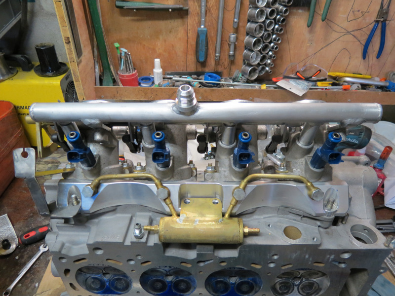

Final Assembly and installation is done on the units, just the small things to finish. I took my time assembling these as from previous experience, you have to be very specific with everything around ITB's as the smallest thing can cause you to remove or strip the lot to redo. One of the reasons I moved the temp sensor slightly. Everything went as planned, even had a brand new accelerator cabled made in under 2 hours, well all good things comes to an end as they say. Well I installed bigger O rings for the fuel rail as was originally supplied with the units, I installed the setup for testing, had the high pressure pump running for about 10 minutes at 3 bar, no leaks. Everything ready for final installations, finished off a few small things and installed everything the following day.
Now you can imagine my face by this time, smiling from ear to ear because the motor will be running for the first time in 5 months. Ready to set the timing etc., once I switched the ignition on all hell broke loose around the injectors with fuel pouring out. A few hard words were thrown around, one thing in life that pisses on my batteries is stuff just failing or acting up without any apparent reason, especially if it was tested in perfect working order before. At the end of the day it turned out that the new O-rings are just too small and I needed a set of 7x4mm units, but as it was Friday evening, I had to wait for Tuesday for stock to arrive.
We continued setting the CAS timing, once the new O-rings were installed we proceeded in starting the motor, pumps on, no leaks, well this was expected as the new O-rings went into the rail so tight. Once my brother opened the butterflies slightly the motor roared into life, without drama, damn I like it when things can be relied on. I must admit I had some help, without the LinkECU's functionality things would be a lot harder, just the mere fact that I can test outputs does make life easier. Every time I work with the thing, it just makes more and more sense to not waste money on "Proudly South African" managements, there is a reason way you pay for what you get.
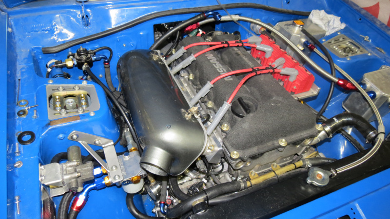
The next steps is to finish the Velocity stacks and sort the idle control valve out, as it is either broken or I need a degree in setting this thing up, because with the single throttle setup idle control was working nicely, but not anymore.
Steering Arms

Well well, during this whole exercise I almost lost a finger, let me explain why you never should get comfortable in front of machines with teeth or is strong enough to swallow body parts.
Seeing that the steering arms was the last big stumbling block on the front suspension that had to be overcome, I was quite eager to get this done, first off I made the bushes that bolts to the strut followed by the ones with the taper for the tie rod ends. Yes this time around I decided I want to simplify things and not use rod ends and adaptors, but rather standard rack ends, shortened and threaded to accept stock toe rod ends. With this configuration I can drive down to the local parts store, buy a set of tie rods and rack ends go home and within an hour have shortened rack ends ready for the spares box.
Everything started with finding the best position of the tie rod to at least have some sort of Ackermann effect, only allow travel of the wheel over the full travel of the rack, while keeping the centre points in the correct places to aid return from full lock and minimize bump steer. All of this was accomplished with a few pieces of flat bar moved around until everything worked, and this is where the accident happened, seeing that we decided to cut the old rack ends shorter to weld one of these flat iron pieces to it, I took a bolt to the bandsaw to cut it off, but rather than holding it in place with the correct tool, I held it in my hand, it caught and tried sucking my finger in and this is where the fingertip and the fine tooth band saw blade made contact. Since I wanted this done the evening in order to order the correct rack ends the following day, I decided to not get stitches and nurse the finger to get it to stop bleeding. Well as murphy wants it, just as I get it to stop bleeding and the pain levels acceptable, I hit it against the inner door as I moved my hand out after turning the steering wheel for my brother.
Just a few things outstanding before I can put the car on its wheels, well if this weekend is a success, I'll be putting it on its wheels at the end of it. Let's hope for the best.
|
|
;)
;)
;)
;)
;)
;)
;)
;)
;)
;)
;)
;)
;)
;)
;)
;)
;)
;)
;)
;)
;)
;)
;)
;)
;)
;)
;)
;)
;)
;)
;)
;)
;)
;)
;)
;)
;)
;)