![[Datsun 1200 encyclopedia]](/wiki/upload/wiki.png)
| Revision as of 20:11, 19 October 2012 ddgonzal (Talk | contribs) <- Previous diff |
Current revision ddgonzal (Talk | contribs) |
||
| Line 1: | Line 1: | ||
| - | [[Category:Engine Electrical System]][[Category:Distributor]] | + | <nowiki>Insert non-formatted text here</nowiki>The early 1200 [[coil]] -- as with nearly all pre-electronic ignition systems -- uses a [[Coil|Ballast resistor]] to drop the voltage supplied to the coil. All 1200s used a ballast resistor until the 1990 models. |
| - | The early 1200 [[coil]] -- as with nearly all pre-electronic ignition systems -- uses a [[Coil|Ballast resistor]] to drop the voltage supplied to the coil. All 1200s used a ballast resistor until the 1990 models. | + | |
| = Early 1200 = | = Early 1200 = | ||
| - | Ballast resistor is located on the right-side Strut tower (#1 in this photo) | ||
| - | <br>[http://datsun1200.com/modules/myalbum/photo.php?lid=14969 http://datsun1200.com/modules/myalbum/photos/14969.jpg] | ||
| - | <br>The resistor is just above the coil, and is a white ceramic thing about 2-1/2 inches long. | ||
| - | |||
| NOTE: The 1973 [[Wiring Diagram]] doesn't show a resistor, but it definitely has one. | NOTE: The 1973 [[Wiring Diagram]] doesn't show a resistor, but it definitely has one. | ||
| Stock wiring harness | Stock wiring harness | ||
| - | <br>[http://datsun1200.com/modules/myalbum/photo.php?lid=23408 http://datsun1200.com/uploads/photos/23408.jpg] | + | <br>{{Album|24889}} |
| - | <table border='1' class='inner' cellspacing='2'> | + | <table class='wiki_table'> |
| - | <tr bgcolor="ccccff"><td>Ballast Resistor</td><td>Color</td><td>Connects To</td></tr> | + | <tr><th>Part</th><th>wire color</th><th>Connects To</th></tr> |
| + | <tr><td>ballast resistor (single-terminal side)</td><td>BW</td><td>to IG terminal of ignition switch</td></tr> | ||
| + | <tr><td>ballast resistor (dual-terminal side)</td><td>BW<br>BR</td><td>to coil '+' terminal<br>to R (START) terminal of ignition switch\*</td></tr> | ||
| + | <tr><td>Coil</td><td>wire color</td><td>Connects To</td></tr> | ||
| + | <tr><td>Coil '+'</td><td>BW</td><td>to ballast resistor dual-connector side</td></tr> | ||
| + | <tr><td>Coil '-'</td><td>B</td><td>to distributor points terminal</td></tr> | ||
| + | </table>\*The coil is supplied full battery voltage during cranking. Hence "R" terminal on ignition switch supplies V+ to coil. | ||
| - | <tr bgcolor=f0f0f0><td>ballast resistor (non-coil side)</td><td>BW</td><td>IG terminal of ignition switch</td></tr> | + | {{Album|23244}} |
| + | <br>NOTE: all the wires indicate are colored BW (black w/white stripe) | ||
| - | <tr bgcolor=f0f0f0><td>ballast resistor (coil side, dual-terminal side</td><td>BW<br>BR</td><td>BR wire to R (START) terminal of ignition switch\*<br>(and)<br>BW to coil '+' terminal</td></tr> | + | The coil wiring does not go through the Fuse Box |
| - | + | <br>{{Photo|Wiring_Ignition.jpg|}} | |
| - | <tr bgcolor="ccccff"><td>Coil</td><td>Color</td><td>Connects To</td></tr> | + | |
| - | + | ||
| - | <tr bgcolor=f0f0f0><td>Coil '+'</td><td>BW</td><td>to ballast resistor dual-connector side</td></tr> | + | |
| - | + | ||
| - | <tr bgcolor=f0f0f0><td>Coil '-'</td><td>B</td><td>to distributor points</td></tr> | + | |
| - | + | ||
| - | </table>\*The coil is supplied full battery voltage during cranking. Hence "R" terminal on ignition switch supplies V+ to coil. | + | |
| - | + | ||
| - | [http://datsun1200.com/modules/myalbum/photo.php?lid=23244 http://datsun1200.com/modules/myalbum/photos/23244.jpg] | + | |
| - | <br>NOTE: all the wires indicate are colored BW (black w/white stripe). | + | |
| == Common Problems == | == Common Problems == | ||
| Line 45: | Line 37: | ||
| BW: Coil + terminal | BW: Coil + terminal | ||
| L: Coil - terminal | L: Coil - terminal | ||
| + | |||
| + | [[Category:Engine Electrical System]][[Category:Distributor]]{{End}} | ||
Current revision
Insert non-formatted text hereThe early 1200 coil -- as with nearly all pre-electronic ignition systems -- uses a Ballast resistor to drop the voltage supplied to the coil. All 1200s used a ballast resistor until the 1990 models.
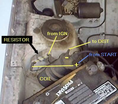
Early 1200
NOTE: The 1973 Wiring Diagram doesn't show a resistor, but it definitely has one.
Stock wiring harness
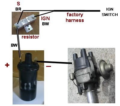
| Part | wire color | Connects To |
|---|---|---|
| ballast resistor (single-terminal side) | BW | to IG terminal of ignition switch |
| ballast resistor (dual-terminal side) | BW BR | to coil '+' terminal to R (START) terminal of ignition switch\* |
| Coil | wire color | Connects To |
| Coil '+' | BW | to ballast resistor dual-connector side |
| Coil '-' | B | to distributor points terminal |
NOTE: all the wires indicate are colored BW (black w/white stripe)
The coil wiring does not go through the Fuse Box

Common Problems
Does your engine start when cranking but immediately die when you release the key to the ON (running) position? Then your resistor is bad or wired incorrectly. As you can see from the diagram, START of the ignition switch supplies full voltage bypassing resistor.
Late 1200
From October 1989, Sunny Truck uses electronic ignition and computerized carburetor. There is NO BALLAST RESISTOR.
Also see: EI Wiring
Coil
BW: unknown. Not needed for old carburetor (non ECU)
BR: Coil + terminal
Distributor
BW: Coil + terminal
L: Coil - terminal