![[Datsun 1200 encyclopedia]](/wiki/upload/wiki.png)
| Revision as of 04:39, 8 October 2017 ddgonzal (Talk | contribs) <- Previous diff |
Revision as of 03:38, 9 October 2019 ddgonzal (Talk | contribs) (->Control Switch) Next diff -> |
||
| Line 17: | Line 17: | ||
| = Control Switch = | = Control Switch = | ||
| A resistor rheostat was used through 1976. This produced significant heat. | A resistor rheostat was used through 1976. This produced significant heat. | ||
| - | <br>{{Photo|B210_1978_38d.jpg|sightings/forum}} | + | <br>{{Album|27738|png|was=B210_1978_38d.jpg-sightings/forum}} |
| <br>This switch went in-between the lamps and Earth/Ground (B wire). | <br>This switch went in-between the lamps and Earth/Ground (B wire). | ||
| - | |||
| - | For 1977 a new active semiconductor rheostat was introduced, which required a 12V IGN feed, but is otherwise wired the same. | ||
| - | |||
| Resistor Rheostat | Resistor Rheostat | ||
| B: Earth/Ground (notched side of connector) | B: Earth/Ground (notched side of connector) | ||
| RL: to lamps | RL: to lamps | ||
| - | {{Photo|B210_1978_38b.jpg|sightings/forum}} | + | {{Album|27740|png|was=B210_1978_38a.jpg-sightings/forum}} |
| + | For 1977 a new active semiconductor rheostat was introduced, which required a 12V IGN feed, but is otherwise wired the same. This one is not load-dependent (works even if one or more bulbs are burned out) and uses less power. | ||
| + | <br>{{Album|27739|png|was=B210_1978_38b.jpg-sightings/forum}} | ||
| Semiconductor Rheostat - Illumination Control | Semiconductor Rheostat - Illumination Control | ||
| B: Earth/Ground | B: Earth/Ground | ||
| GW: to lamps & Lighting Switch from Fuse Box (RG) | GW: to lamps & Lighting Switch from Fuse Box (RG) | ||
| GY: to lamps | GY: to lamps | ||
| - | {{Photo|B210_1978_38a.jpg|sightings/forum}} | ||
| - | Pin-Out | + | {{Album|27741|png|was=B210_1978_38c.jpg-sightings/forum}} |
| - | <br>{{Photo|B210_1978_38c.jpg|sightings/forum}} | + | |
| - | B310 Illumination Control | + | B310 Illumination Control controlled these lamps: |
| * Heater Control lamp | * Heater Control lamp | ||
| * Radio lamp | * Radio lamp | ||
Revision as of 03:38, 9 October 2019
GL and GX trim Datsun 1200s used illuminated electrical switch knobs. For 1973 all USA 1200s adopted the illuminated knobs. B210 also used this as standard fitment in Japan and USA.
Contents |
Overview
A variable knob was turned to progressively dim the lamps.
H70 Type: Green knobs with words and illumination.
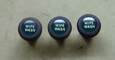
* Wipe Wash knob
* Heater Control knob
* Cigar Lighter knob
* Auto-trans shift indicator lamp
From 1976
* Clock lamp
* Radio lamp
Control Switch
A resistor rheostat was used through 1976. This produced significant heat.
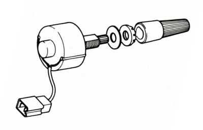
This switch went in-between the lamps and Earth/Ground (B wire).
Resistor Rheostat
B: Earth/Ground (notched side of connector)
RL: to lamps

For 1977 a new active semiconductor rheostat was introduced, which required a 12V IGN feed, but is otherwise wired the same. This one is not load-dependent (works even if one or more bulbs are burned out) and uses less power.
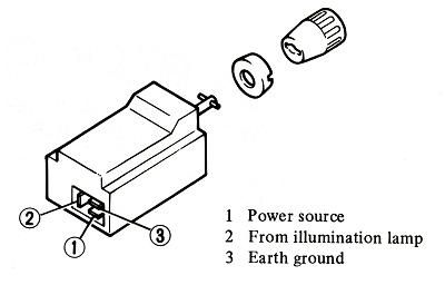
Semiconductor Rheostat - Illumination Control
B: Earth/Ground
GW: to lamps & Lighting Switch from Fuse Box (RG)
GY: to lamps
B310 Illumination Control controlled these lamps:
* Heater Control lamp
* Radio lamp
* Ash tray lamp
* Cigarette Lighter lamp
* Clock lamp
* To dash rotary connector
  Three lamps - Instrument Panel
  * Pin 5
  * Pin 6
* Shifter lamp (Automatic Transmission)
Australia
Australia 1200s use a two-position bright/dim switch built into the Lighting Switch. It is not a rheostat (variable). The knob is twisted (rotated) to use either bright or dim position.
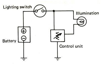
Wiring
See Wiring Diagrams
Part Numbers
See main article: Switch Part Numbers