![[Datsun 1200 encyclopedia]](/wiki/upload/wiki.png)
Contents |
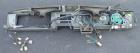
Speedometer
The speedometer has a light for use at night. See the lamp section.
1972 Facelift speedometer has special switch:
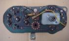
Speed Switch
Ute Amplifier Speed Switch
Amplifier for B120 ute Throttle Opener Assembly (see Emission Controls). It's only fitted to the Manual Transmission models.
The speed detecting switch is part of the speedometer assembly and is installed in the speedometer. The amplifier prevents damage to the speed detecting switch which actuate the throttle opener only when the car speed is above 10km/h.Pub No. SM6E-EMC0A0, Page EC-11
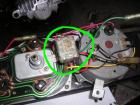
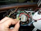
Switch has three wires. It looks as if, from these photos:
- Red: Ground ? fits on round-side connector
- Black: -- goes to Red wire coming out of top center of panel
- Green: Unknown
Double-check before using.
USA Amplifier Speed Switch
USA model from 0772 use an amplifier speed switch.
- 25035-H7000 ASSY-AMPLIFIER SPEED SWITCH
Cluster Gauges
The cluster gauge contains:
- Fuel Gauge (Petrol/Gas gauge)
- Water temperature gauge
- Oil pressure indicator lamp (see "Troubleshooting Oil Light" below)
- Indicators lamp (see "Troubleshooting Dash Lights" below)
- High beam indicator lamp
- Turn Signal indicator lamps
- Brake failure lamp
The coolant/water temperature gauge incorporates a voltage regulator.
- If both the water and fuel gauges are off, suspect the regulator
- If only one gauge is incorrect, suspect a bad connection, usually at the sensor
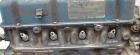
- Temp sensor at cylinder head (on right side of head, at the very front):
-
- Fuel sensor at fuel tank
- Temp sensor at cylinder head (on right side of head, at the very front):
Fuel Gauge
Back at the Fuel tank, there is a single Yellow (Y) wire on the sender.
- connects to Y wire in the main body harness
- connects to Y wire in the dash wiring harness
- connects to Y wire in the cluster connector
The sender is grounded through the tank body.
Troubleshooting Fuel Gauge
A non-working Fuel gauge is usually one of three things:
- Bad 'sender' (sensor) which is in the fuel tank
- Bad gauge in the dash
- Bad wiring
- Pull the Fuel sensor wire (Yellow) off at fuel tank
- Ground/earth this wire
- turn IGN switch on and observe gauge:
- Gauge still dead. It is not caused by fuel sender. Check for loose wiring, at back of dash, or at dash wiring harness connectors
- Gauge goes to Full. Bad sender
Sender Resistance Check
You can also check the Resistance of the sender. Remove Yellow wire and measure between terminal and bare metal of sender: It should read higher than 10 ohms, but less than 88 ohms. If it is higher or lower than this range, replace the Sender.
Sender Full-Range Test
- Remove Fuel sender from tank. This is fairly easy with Sedan, or with ute after removing inspection cover from tray. Not easy with Coupe.
- With wiring connected to sender, ground/earth the top of the sender to body ground (using a jumper wire)
- Float down, gauge should read below E
- Float up, gauge should read above F
The Fuel Tank Sender (fuel sensor) has a float, and as it rises and falls with the fuel level, it varies the electrical resistance (Ohms) of the sensor. As measured by club members, by moving the float up and down from stop to stop:
- 12 ohms fully up
- 88 ohms fully down
- 35 ohms half full (per Nissan Factory Service Manual)