[< Previous 194 195 196 197 198 199 200 Next >]
[< Previous 194 195 196 197 198 199 200 Next >]
The comments are owned by the poster. We aren't responsible for their content.
| Poster |
Thread |
| ddgonzal |
Posted: 2004/1/18 5:21 Updated: 2004/1/18 5:21 |
Moderator   Joined: 2001/5/3 From: Kent, WA Posts: 31866 |
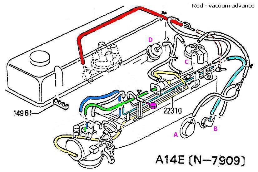
 Re: B310 EGI vacuum hose diagram It looks like (not 100% sure):
A = (???) EGR valve
B = temperature-based vacuum switch
C = 14771-H9215 VALVE ASSY-VVT
D = 22670-N4700 REGULATOR ASSY-PRESSURE
The switch on top middle on the manifold (which green and yellow hoses connect to) =
14956-H7206 VALVE ASSY-SOLENOID EGR CUT
(?) One of the hoses on throttle body = ported vacuum (for distributor advance). It will be the one on the filter side of the throttle butterfly.
|
|
|


 Mechanical
 Fuel Injection

 0.00 (0 votes)
