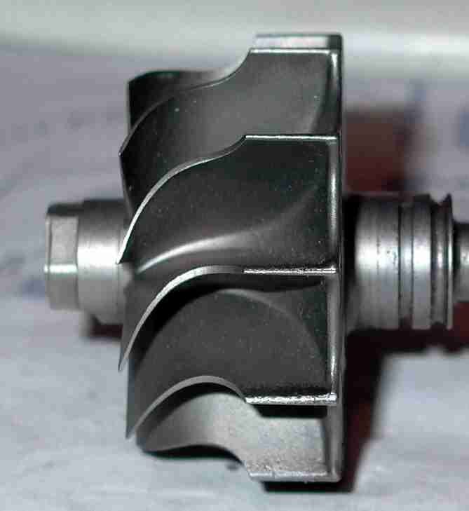
Main :  Misc TURBINE WHEEL SHOWING BLADE CONFIGURAION Misc TURBINE WHEEL SHOWING BLADE CONFIGURAION | |
|
[< Previous 6482 6483 6484 6485 6486 6487 6488 Next >]
[< Previous 6482 6483 6484 6485 6486 6487 6488 Next >]
The comments are owned by the poster. We aren't responsible for their content.
| Poster |
Thread |
| phunkdoktaspok |
Posted: 2004/3/9 13:33 Updated: 2004/3/9 13:33 |
No life (a.k.a. DattoMaster)   Joined: 2002/9/23 From: Posts: 2809 |
 Re: TURBINE WHEEL SHOWING BLADE CONFIGURAION This makes it more visible then my pic.
Does back cutting involve machining down the lefthand side of the turbine or just actually thinning out the lefthand side of the blades? If its the latter wouldnt this lead to turbine failure?( ie, bits breaking off the blades)
Cheers Steve
|
|
|
|
| Poster |
Thread |
| feral |
Posted: 2004/3/9 21:22 Updated: 2004/3/9 21:22 |
Home away from home   Joined: 2002/5/1 From: Millgrove Vic OZ Posts: 985 |
 Re: TURBINE WHEEL SHOWING BLADE CONFIGURAION Material is taken of the end of the blade. This opens the blade discharge area, and changes the angle of discharge.
Increasing the housing clearance at the discharge area achieves much the same effect but efficiency drops of rapidly as clearance is increased.
|
|
|
|


 Misc
Misc

 0.00 (0 votes)


