![[Datsun 1200 encyclopedia]](/wiki/upload/wiki.png)
| Revision as of 06:59, 18 May 2009 ddgonzal (Talk | contribs) <- Previous diff |
Revision as of 07:22, 18 May 2009 ddgonzal (Talk | contribs) Next diff -> |
||
| Line 7: | Line 7: | ||
| A volt-ohm-milliammeter (VOM) may be used to diagnose transistor ignition malfunctions. | A volt-ohm-milliammeter (VOM) may be used to diagnose transistor ignition malfunctions. | ||
| - | Use this scale: | + | Use these scales: |
| <br>DC: 20V | <br>DC: 20V | ||
| - | <br>Ohms: 1000 | ||
| <br>AC: 10V | <br>AC: 10V | ||
| + | <br>Ohms: 1000 | ||
| <br>Ohms: 50,000 | <br>Ohms: 50,000 | ||
| Line 18: | Line 18: | ||
| - | == Step 5 Power Supply Circuit == | + | = Step 5 Power Supply Circuit = |
| # IGN key ON, engine not running | # IGN key ON, engine not running | ||
| # connect Voltmeter (20V scale) between distributor case and the "B" connection (stem of T) | # connect Voltmeter (20V scale) between distributor case and the "B" connection (stem of T) | ||
| Line 24: | Line 24: | ||
| Results: | Results: | ||
| * below 11.5 volts. Problem. Check fuse and wiring | * below 11.5 volts. Problem. Check fuse and wiring | ||
| - | * 11.5 - 12.5 volts. This test OK. Proceed to Test 6 | + | * 11.5 - 12.5 volts. This test OK. Proceed to Step 6 |
| = Step 6 Power Supply (Cranking) = | = Step 6 Power Supply (Cranking) = | ||
| Line 34: | Line 34: | ||
| Results: | Results: | ||
| * Voltage more than 1V below Battery cranking voltage (or below 8.6V). Check ignition switch, fuse and wiring | * Voltage more than 1V below Battery cranking voltage (or below 8.6V). Check ignition switch, fuse and wiring | ||
| - | * Voltage close to battery cranking voltage (no more than 1V lower) AND better than 8.6V. This test is OK. Proceed to Test 7 | + | * Voltage close to battery cranking voltage (no more than 1V lower) AND better than 8.6V. This test is OK. Proceed to Step 7 |
| = Step 7 Ignition Primary Circuit = | = Step 7 Ignition Primary Circuit = | ||
| Line 41: | Line 41: | ||
| Results: | Results: | ||
| - | * below 11.5 volts. Problem. Proceed with Test 8 | + | * below 11.5 volts. Problem. Proceed with Step 8 |
| - | * 11.5 - 12.5 volts. This test OK. Proceed with Test 9 | + | * 11.5 - 12.5 volts. This test OK. Proceed with Step 9 |
| - | + | ||
| = Step 8 Coil Primary Circuit = | = Step 8 Coil Primary Circuit = | ||
| # Key OFF | # Key OFF | ||
| - | # coil wire removed from coil | + | # Ignition Coil wire removed from coil |
| - | # | + | # Ohmmeter at 1x (lowest) range |
| + | # Connect ohmmeter between Coil's two terminals (+ and -) | ||
| + | Results: | ||
| + | * 0.84-1.02 ohms. Ignition coil primary winding is O.K, so to solve the problem, check the ignition switch, fuse and wiring from ignition switch to coil and IC unit | ||
| + | * Less than 0.84 or more than 1.02 ohms. Coil is bad. Replace the coil. | ||
| + | *: NOTE This is for the matching "high energy" Nissan coil. If you are using the stock Datsun 1200 points-based coil, see [[Ignition Coil]] | ||
| + | = Step 9 IC Unit Ground Circuit = | ||
| + | Checking "voltage drop" of the ciruit while in use. | ||
| + | |||
| + | # Voltmeter at 20V scale | ||
| + | # Connect voltmeter between distributor case and Battery NEGATIVE terminal | ||
| + | # Crank engine and observe voltmeter | ||
| + | |||
| + | Results: | ||
| + | * 0.5 volts or less: OK. Proceed to Step 10 | ||
| + | * More than 0.5 volts: Bad ground. Check distributor ground, wiring from chassis ground to battery include cable connections | ||
| = Step 10 Pick-up Coil Resistance = | = Step 10 Pick-up Coil Resistance = | ||
| + | Pick-Up Coil | ||
| + | <br>http://datsun1200.com/uploads/thumbs/1580.jpg | ||
| + | |||
| Check the pickup resistance: | Check the pickup resistance: | ||
| # Key OFF | # Key OFF | ||
| Line 59: | Line 76: | ||
| Results: | Results: | ||
| - | * It should be about 400 ohms. Proceed to Test 11 | + | * It should be about 400 ohms. Proceed to Step 11 |
| * If "substantially" lower or higher than 400 ohms, the pickup is either bad or a wire is pinched or shorted. | * If "substantially" lower or higher than 400 ohms, the pickup is either bad or a wire is pinched or shorted. | ||
Revision as of 07:22, 18 May 2009
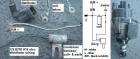
How to test your 1978-1982 factory Datsun "matchbox" distributor, from the Nissan factory service manual. Matchbox is a nickname for the "IC ignition unit".
For B310 Electronic Distributor Swap
 ]
]
Contents |
General Instructions
A volt-ohm-milliammeter (VOM) may be used to diagnose transistor ignition malfunctions.
Use these scales:
DC: 20V
AC: 10V
Ohms: 1000
Ohms: 50,000
If possible test with components at operating temperature -- this will help find intermittent problems that only occur when the parts are HOT.
It is not necessary to disconnect the harness connectors when performing the following tests.
Step 5 Power Supply Circuit
- IGN key ON, engine not running
- connect Voltmeter (20V scale) between distributor case and the "B" connection (stem of T)
Results:
- below 11.5 volts. Problem. Check fuse and wiring
- 11.5 - 12.5 volts. This test OK. Proceed to Step 6
Step 6 Power Supply (Cranking)
- Pull coil wire from cap and ground it
- Set Voltmeter to 20V DC scale
- connect Voltmeter between distributor case and the "B" connection (stem of T)
- Crank engine (key at START) and observe voltage
Results:
- Voltage more than 1V below Battery cranking voltage (or below 8.6V). Check ignition switch, fuse and wiring
- Voltage close to battery cranking voltage (no more than 1V lower) AND better than 8.6V. This test is OK. Proceed to Step 7
Step 7 Ignition Primary Circuit
- IGN key ON, engine not running
- connect Voltmeter (20V scale) between distributor case and the "C" connection (head of T)
Results:
- below 11.5 volts. Problem. Proceed with Step 8
- 11.5 - 12.5 volts. This test OK. Proceed with Step 9
Step 8 Coil Primary Circuit
- Key OFF
- Ignition Coil wire removed from coil
- Ohmmeter at 1x (lowest) range
- Connect ohmmeter between Coil's two terminals (+ and -)
Results:
- 0.84-1.02 ohms. Ignition coil primary winding is O.K, so to solve the problem, check the ignition switch, fuse and wiring from ignition switch to coil and IC unit
- Less than 0.84 or more than 1.02 ohms. Coil is bad. Replace the coil.
- NOTE This is for the matching "high energy" Nissan coil. If you are using the stock Datsun 1200 points-based coil, see Ignition Coil
Step 9 IC Unit Ground Circuit
Checking "voltage drop" of the ciruit while in use.
- Voltmeter at 20V scale
- Connect voltmeter between distributor case and Battery NEGATIVE terminal
- Crank engine and observe voltmeter
Results:
- 0.5 volts or less: OK. Proceed to Step 10
- More than 0.5 volts: Bad ground. Check distributor ground, wiring from chassis ground to battery include cable connections
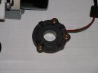
Step 10 Pick-up Coil Resistance
Pick-Up Coil
Check the pickup resistance:
- Key OFF
- ohmmeter between the two wires on the matchbox (red & green wires -- NOT the T-connector).
- set VOM to 1000 ohm scale
Results:
- It should be about 400 ohms. Proceed to Step 11
- If "substantially" lower or higher than 400 ohms, the pickup is either bad or a wire is pinched or shorted.
Step 11 Pick-up Coil Output
Output while cranking. Use ANALOG voltemeter.
- Engine at or above normal operating temperature (HOT) if possible
- VOM at 5V AC or 10V AC scale
- Connect Voltmeter to body of distributor (ground) and internal wire closest to the T-connector
- Remove coil wire from cap and ground it
- Observe analog Voltmeter while cranking engine
Results:
- Needle wavers. OK. But if "no Spark" condition still exists, replace IC ignition unit
- Needle steady. Problem.
- Check physical condition of pick-up coil and reluctor
-
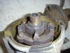
- Reluctor (4-tooth rotating part). Stator (4-teeth ring)
-
- Check wiring and connections between coil and IC ignition unit (the matchbox)
- Check physical condition of pick-up coil and reluctor