![[Datsun 1200 encyclopedia]](/wiki/upload/wiki.png)
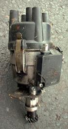
How to test your 1978-1982 factory Datsun "matchbox" distributor, from the Nissan factory service manual. Matchbox is a nickname for the "IC ignition unit" bolted to the side of this type of Hitachi distributor. The tests are for "No Spark" condition.
For B310 Electronic Distributor Swap
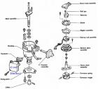 part names
Spark Testing
- Remove coil wire from distributor cap
- Lay wire end on top of the unpainted metal engine surface -- with metal end 4 to 5 mm from metal (not touching the metal)
- Observe the wire end while cranking engine (Key to START position). You should be able to see it from the drivers seat through the windshield.
Result: Do you see a regular pattern of yellow sparks at the clearance?
- YES: it's OK.
- NO, no spark or irregular spark. Proceed with the testing Step 1.
General Instructions
A volt-ohm-milliammeter (VOM) may be used to diagnose transistor ignition malfunctions. One of the tests requires an analog voltmeter, so old-fashioned meter is good.
Use these scales:
DC: 20V
AC: 10V
Ohms: 1000
Ohms: 50,000
If possible test with components at operating temperature -- this will help find intermittent problems that only occur when the parts are HOT.
It is not necessary to disconnect the harness connectors when performing the following tests.
During the tests, when a fault is found, correct the problem before continuing. If all tests are OK, replace the IC unit.
DO NOT REPLACE THE UNIT UNTIL ALL TESTS HAVE BEEN COMPLETED AND INDICATE "O.K.".
Step 1 Battery Voltage
This is the foundation of testing.
- Key OFF
- Connect Voltmeter directly to battery terminals (NOT THE CABLE ENDS)
Results:
- 11.5 to 12.5 volts. OK. Proceed to Step 2
- Below 11.5 volts. Charge battery before continuing
Step 2 Cranking Voltage
- Remove coil wire from cap and ground it
- Connect Voltmeter to battery cable ends at battery
- Observe Voltmeter while cranking engine for approximately 15 seconds
Results:
- Voltage higher than 9.6V. OK. Proceed to Step 3
- Voltage less than 9.6V. Battery or Starter or wiring connection/corrosion problem. Fix before proceeding.
Step 3 Secondary Wires
- Ohmmeter at 50K scale
- Plug wires still on the Distributor Cap
- Measure resistance of each Spark plug wire (high tension cable) from terminal inside cap to end of wire
Results:
- Less than 30K Ohms. OK. Proceed to Step 4
- More than 30K Ohms. Bad. Replace wires or cap as required
Step 4 Coil Secondary Circuit
- Key OFF
- Remove coil wire
- Ohmmeter between coil wire center terminal and NEG terminal of coil
Result:
- 8,200 to 12,400 ohms. OK. Proceed to Step 5
- Lower or higher. Faulty coil. Replace.
Step 5 Power Supply Circuit
- IGN key ON, engine not running
- connect Voltmeter (20V scale) between distributor case and the "B" connection (stem of T)
Results:
- below 11.5 volts. Problem. Check fuse and wiring
- 11.5 - 12.5 volts. This test OK. Proceed to Step 6
Step 6 Power Supply (Cranking)
- Pull coil wire from cap and ground it
- Set Voltmeter to 20V DC scale
- connect Voltmeter between distributor case and the "B" connection (stem of T)
- Crank engine (key at START) and observe voltage
Results:
- Voltage more than 1V below Battery cranking voltage from Step 2 (or below 8.6V). Check ignition switch, fuse and wiring
- Voltage close to battery cranking voltage from Step 2 (no more than 1V lower) AND better than 8.6V. This test is OK. Proceed to Step 7
Step 7 Ignition Primary Circuit
- IGN key ON, engine not running
- connect Voltmeter (20V scale) between distributor case and the "C" connection (head of T)
Results:
- below 11.5 volts. Problem. Proceed with Step 8
- 11.5 - 12.5 volts. This test OK. Proceed with Step 9
Step 8 Coil Primary Circuit
- Key OFF
- Ignition Coil wire removed from coil
- Ohmmeter at 1x (lowest) range
- Connect ohmmeter between Coil's two terminals (+ and -)
Results:
- 0.84-1.02 ohms. Ignition coil primary winding is O.K, so to solve the problem, check the ignition switch, fuse and wiring from ignition switch to coil and IC unit
- Less than 0.84 or more than 1.02 ohms. Coil is bad. Replace the coil.
NOTE This is for the matching "high energy" Nissan factory-fitted coil: Type CIT-30. (12V non-resistor Nissan 22433-H7280, Bosch 00200, Beck/Arnley 1800039, AC Delco E525 or C502 (replaces F519 #12321584), Standard Motor Products UF-4/UF-4T)
IF you are using the stock Datsun 1200 points-based coil, see Ignition Coil for resistance specifications.
Step 9 IC Unit Ground Circuit
Checking "voltage drop" of the ciruit while in use.
- Voltmeter at 20V scale
- Connect voltmeter between distributor case and Battery NEGATIVE terminal
- Crank engine and observe voltmeter
Results:
- 0.5 volts or less: OK. Proceed to Step 10
- More than 0.5 volts: Bad ground. Check distributor ground, wiring from chassis ground to battery include cable connections
Step 10 Pick-up Coil Resistance
Pick-Up Coil
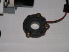
Check the pickup resistance WITH ALL WIRES CONNECTED:
- Key OFF
- ohmmeter between the two wires on the matchbox (red & green wires -- NOT the T-connector).
- set VOM to 1000 ohm scale
Results:
- It should be about 400 ohms. Proceed to Step 11
- If "substantially" lower or higher than 400 ohms, the pickup is either bad or a wire is pinched or shorted.
Step 11 Pick-up Coil Output
Output while cranking. Use ANALOG voltemeter.
- Engine at or above normal operating temperature (HOT) if possible
- VOM at 5V AC or 10V AC scale
- Connect Voltmeter to body of distributor (ground) and internal wire closest to the T-connector
- Remove coil wire from cap and ground it
- Observe analog Voltmeter while cranking engine
Results:
- Needle wavers. OK. But if "no Spark" condition still exists, replace IC ignition unit
- Needle steady. Problem.
- Check physical condition of pick-up coil and reluctor
-
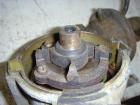
- Reluctor (4-tooth rotating part). Stator (4-teeth ring)
-
- Check wiring and connections between coil and IC ignition unit (the matchbox)
- Check physical condition of pick-up coil and reluctor