|
|
[< Previous 6143 6144 6145 6146 6147 6148 6149 Next >] 
A series injection manifold
 who_your_datty_1200 who_your_datty_1200  2004/7/16 11:50 2004/7/16 11:50  Tell a friend Tell a friend
 9099 9099  48 48  10.00 (2 votes) 10.00 (2 votes)
| Its on an A14 at the moment and needs a clean up, but its all there. I just have to make a in inlet hose. |
|
|
[< Previous 6143 6144 6145 6146 6147 6148 6149 Next >]
The comments are owned by the poster. We aren't responsible for their content.
| Poster |
Thread |
| killer1200 |
Posted: 2005/4/16 11:52 Updated: 2005/4/16 11:52 |
No life (a.k.a. DattoMaster)   Joined: 2004/5/28 From: Adelaide, South Australia Posts: 1817 |
 Re: A series injection manifold what's the go with the piping i don't think it will be going throught the bonnet?
|
|
|
|
| Poster |
Thread |
| who_your_datty_1200 |
Posted: 2005/4/16 15:27 Updated: 2005/4/16 15:27 |
No life (a.k.a. DattoMaster)  Joined: 2004/2/26 From: Posts: 1440 |
Re: A series injection manifold A modiftied trottle body has fixed that problem. As you can see by the picture I cut off the extra bit of pipe work,  |
|
|
|
|
| Poster |
Thread |
| who_your_datty_1200 |
Posted: 2006/5/23 9:39 Updated: 2006/5/23 9:39 |
No life (a.k.a. DattoMaster) Joined: 2004/2/26 From: Posts: 1440 |
Re: A series injection manifold Im not sure if I have posted this picture up before, but here's what Monty's engine bay looks like now.............  |
|
|
|
| Poster |
Thread |
| Dodgeman |
Posted: 2004/7/18 11:25 Updated: 2004/7/18 11:25 |
No life (a.k.a. DattoMaster) 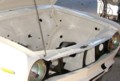 Joined: 2003/6/27 From: Southern Tablelands N.S.W. Australia Posts: 8287 |
Re: A series injection manifold You seem to be stressing out big time here, so i'l tell what I can do for you.
I'l just take that nerve wracking bundle of drama off your hands for you & I'l even give you some money for it so that the whole exercise won't be a total loss for you. I'm sure that i can find a place on my shelf for it & you can recover your health & mental condition.
Don't thank me, that's what friends are for.
Chris
|
|
|
|
| Poster |
Thread |
| who_your_datty_1200 |
Posted: 2004/7/18 11:28 Updated: 2004/7/18 11:28 |
No life (a.k.a. DattoMaster) Joined: 2004/2/26 From: Posts: 1440 |
Re: A series injection manifold OMG thank you DM thats the best laugh I have had for years, so now my stress levels are now back to normal!!!
I am still laughing!!!!!!!!!!!
|
|
|
|
|
| Poster |
Thread |
| who_your_datty_1200 |
Posted: 2004/7/21 9:48 Updated: 2004/7/21 9:48 |
No life (a.k.a. DattoMaster) Joined: 2004/2/26 From: Posts: 1440 |
Re: A series injection manifold Ok I have now got the computer 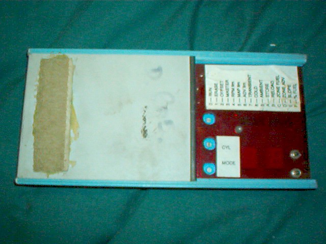 And I also got a sheet of what has been done to the head of the A14. Dbl valve springs at 75 lbs camlift .292" valve lift at 1.4 ratio .409" duration at .050" camlift 220 degs Lobe separation (max lift) 106 degs ATDC 110 degs BTDC Lobe separation 108 degs Cam timing at .050" camlift IN.O. 40 TDC IN.C. 36 ABDC EX.O. 40BBDC If that means anything to someone please tell me LOL cos I have know idea!!!! It was done by Kelford Camtech in CHCH NZ |
|
|
|
|
| Poster |
Thread |
| Dodgeman |
Posted: 2004/7/21 11:59 Updated: 2004/7/21 11:59 |
No life (a.k.a. DattoMaster) Joined: 2003/6/27 From: Southern Tablelands N.S.W. Australia Posts: 8287 |
Re: A series injection manifold W_Y_D_1200
In answer to your PM i will say that some of the info is a little misleading, but i will give it a try.
Double Valve springs [this is good] I'm guessing that they exert 75 lbs of force on the valve when it is closed.
Camlift. The tappet, or lifter, rises .292" at max cam lift.
Valve lift at 1.4 ratio.
If your rockers were of a 1.4 to 1 ratio then the valve would lift .409" off it's seat, but i have always believed that Datsun A series rockers were 1.5 to 1 ratio, so the valve would lift .438" from it's seat at max lift & with zero tappet clearance. [thats a lot for a little motor]
Duration At.050 camshaft lift 220 degrees.
This is an industry standard type of spec. It is widely believed that no significant airflow past the valve exists at anything less than .050" of cam lift. This would translate to .075 of valve lift, less the valve lash, & the figure quoted, is the number of degrees of crankshaft rotation between the time the valve lifter has reached .050" on it's way up, untill it reaches that same .050" on it's way back down again. 220 degrees sounds a bit like a fast road cam to me. Since this figure is quoted only once, i will assume that it is the same for both inlet & exhaust cycles.
The next line makes no sense to me at all.
Lobe separation. If you draw an imaginary line from the center of the camshaft to the tip of the lobes you can see that they are a certain number of degrees apart. 110 degrees is a common separation & bringing them together or separating them further will tailor the performance characteristics even more.
The Wade cams site lists eight cams for A series Datsuns starting with what looks to be a GX replacement with 110 degrees of lobe separation, up to the "race only" grinds with 106 degrees of separation. At 108 degrees, your cam looks to be a bit o' hot stuff for a road car.
Cam timing at .050" cam lift.
Again, this is a more practical measurement then the "advertised [zero lift] specifications"
The figures quoted are not too clear, but TDC means "top dead center" while BDC clearly means "bottom dead center." The letters before these [B or A] simply mean before, or after, so a cam with specs like "inlet opens 15 btdc, closes 25 abdc @ .050 lift' would give you 220 degrees of duration. The exhaust is often just the reverse of the inlet, ie, Exh opens 25 bbdc, closes 15 atdc.
This imaginary cam would give you 30 degrees of overlap, that being the number of degrees of crankshaft rotation where the two valves are open together. One just opening, the other just closing
The more the overlap, the more the rump rump rump, & this is not so good for a road car, but is only a worry to a racer when moving around in the pits.
It seems to be a good cam, but is it just a bit too good for street use? Hopefully, some others will kick in with their own opinion.
|
|
|
|
|
| Poster |
Thread |
| who_your_datty_1200 |
Posted: 2004/7/21 12:14 Updated: 2004/7/21 12:14 |
No life (a.k.a. DattoMaster) Joined: 2004/2/26 From: Posts: 1440 |
Re: A series injection manifold Thanks Chris!!!!
I might take a pic of the sheet and email it to you so you can have a good look.
Sounds like its a bit of a hot cam............... COOL!!!!! I think that I am going to have a weeeee bit of fun with this car when the motor goes in!!!! Now I cant wait!!!
|
|
|
|
|
| Poster |
Thread |
| Dodgeman |
Posted: 2004/7/21 13:14 Updated: 2004/7/21 13:14 |
No life (a.k.a. DattoMaster) Joined: 2003/6/27 From: Southern Tablelands N.S.W. Australia Posts: 8287 |
Re: A series injection manifold Sometimes fiddling with the valve lash [tappet clearance] can help fine tune a cam, within limits. By opening up the tappet clearance, the valves will open a little later, lift a few thou less, & close a little sooner.
Sometimes this is all thats needed to tame down a hairy cam just enough to make it driveable untill you can make it to the track or strip.
The young blokes 1200 coupe with the 1434cc 1200 engine is running about 17 thou [or a little more] tappet clearance. This has softened the cam "event" enough to make it run quite reasonably. [sort of] When he wants to get nasty, he just closes them up to about 12 thou. The diference in cam performance [with THIS cam] is noticeable. We have no idea what the specs are. This cam was salvaged from a junk ex-speedway motor & it looked OK.
|
|
|
|
|
| Poster |
Thread |
| who_your_datty_1200 |
Posted: 2004/7/21 13:20 Updated: 2004/7/21 13:20 |
No life (a.k.a. DattoMaster) Joined: 2004/2/26 From: Posts: 1440 |
Re: A series injection manifold It says on the sheet that the tappets in when hot set to .012" and ex cold .014"
Dont know if that helps?
|
|
|
|
|
| Poster |
Thread |
| Dodgeman |
Posted: 2004/7/21 13:36 Updated: 2004/7/21 13:36 |
No life (a.k.a. DattoMaster) Joined: 2003/6/27 From: Southern Tablelands N.S.W. Australia Posts: 8287 |
Re: A series injection manifold Sometimes when a cam is a bit savage, it can be tamed a bit by opening the settings from the recomended figures. You gotta install & run it to see what it's like first.
|
|
|
|
|
| Poster |
Thread |
| who_your_datty_1200 |
Posted: 2004/7/21 13:41 Updated: 2004/7/21 13:41 |
No life (a.k.a. DattoMaster) Joined: 2004/2/26 From: Posts: 1440 |
Re: A series injection manifold Yeah very true, I know that when I show that sheet to Bart he's going to be tempted to help me put it in the hole!!
|
|
|
|
|
| Poster |
Thread |
| AFRacer |
Posted: 2004/7/21 14:35 Updated: 2004/7/21 14:35 |
Home away from home   Joined: 2002/3/7 From: Little Rock, AR Posts: 639 |
Re: A series injection manifold Stock Datsun rocker arm ratio is 1.44:1 Nissan Motorsports sells a little bit hotter rocker arm that is 1.5:1 ratio. I put a set of these on my A15 and it seemed to run a little better (not much).
I am also running a camshaft that is very similar to the stats of your cam, it was a decent little street cam. Mine was 229 duration at .050" lift, and total lift was .414" with stock rocker arms. I can't remember what the lobe separation was, but the cam grinder recommended running the valve lash at .018" which I have always done since it's been running. I never thought about running less valve lash to give a little bit hotter performance...I wouldn't mind putting it on a dyno and close up the lash to see if that really makes a difference.
The way lobe separation was explained to me is that a tighter one...say around 108 degrees, would give more rumpity rump at idle but more upper end power and possibly rev a little higher. Something a little wider, say 114 degrees would give a much smoother idle and have a bit more torque and low end power.
Regardless, I think you have a decent little cam, perfect for a street car. I have been able to get over 35 miles per gallon with my cam which is a little more aggressive than yours and twin SU's. You should get a little more power and gas mileage though with the EFI. I think you'll be happy with it all!
-Andy
|
|
|
|
|
| Poster |
Thread |
| ddgonzal |
Posted: 2004/7/21 16:33 Updated: 2004/7/21 16:33 |
Moderator   Joined: 2001/5/3 From: Kent, WA Posts: 31814 |
Re: A series injection manifold Quote: I dont know what the thing is that sits on top of the maniflod with the orange wires coming out of it??? I've never seen anything like that. Could it be a resistor/convertor for the type of injector (high resistance vs. low resistance injectors)? Maybe your ecu needs a certain type. Quote: And just below that is that the air flow meter with the vaccum hosebeside it?? I don't see an airflow meter. The plenum is the large aluminum part. The round thing to the right is the fuel regulator. The stock Datsun setup doesn't use Mass Airflow meter. It uses a vane-type meter, so it's not a true speed-density system either. who_your_datty_1200, take a look at this article, it has pictures and explains how the stock Datsun setup works. The A14E manifold/injector/fuelrail setup you have here uses the exact same injectors as the Z22 engine circa 1981. OEM Nissan EFI system |
|
|
|
|
| Poster |
Thread |
| who_your_datty_1200 |
Posted: 2004/7/22 12:43 Updated: 2004/7/22 12:43 |
No life (a.k.a. DattoMaster) Joined: 2004/2/26 From: Posts: 1440 |
Re: A series injection manifold I emailed link to day and they sent me a manual on the computer, so when I get it in the car I can tune it!!! and the bonus is that it can run boost so the turbo can just bolt on!!!! no need to get another computer!!!
AFRacer I was hoping for a bit of a hot cam, but hey for the price I paid for all of this, I am not complaining at all!!! As like you said its going to be a nice street cam. It should give some of these wannbe boy racers a weeee bit of a suprise!!!!
DD the orange wire thingie is so I am told a resistor, but what it is doing not sure yet. Thanks for the link to that page, and I have copyed the text and pictures for reference.
Cheers
Blair
|
|
|
|
|
| Poster |
Thread |
| bobs1200 |
Posted: 2004/10/16 6:36 Updated: 2004/10/16 6:36 |
Home away from home  Joined: 1999/9/13 From: Tracy ,Ca Posts: 341 |
Re: A series injection manifold the block on top of manifold with orange wires attached could be a dropping resistor for the injectors most early inectors use lower voltage for longer life of the injector and injector driver
|
|
|
|
|
| Poster |
Thread |
| who_your_datty_1200 |
Posted: 2004/10/16 8:21 Updated: 2004/10/16 8:21 |
No life (a.k.a. DattoMaster) Joined: 2004/2/26 From: Posts: 1440 |
Re: A series injection manifold Hey cheers for that as I was wondering what it was for
|
|
|
|
|
| Poster |
Thread |
| who_your_datty_1200 |
Posted: 2005/3/19 14:56 Updated: 2005/3/19 14:56 |
No life (a.k.a. DattoMaster) Joined: 2004/2/26 From: Posts: 1440 |
Re: A series injection manifold I need a wiring diagram for this. Now that its slowly coming together again, I have found that it is missing some bits of the wiring!!  |
|
|
|
|
| Poster |
Thread |
| matbighat |
Posted: 2005/3/19 17:14 Updated: 2005/3/19 17:14 |
No life (a.k.a. DattoMaster)  Joined: 2001/1/30 From: California Posts: 2973 |
Re: A series injection manifold I'm still mixed on the factory injected setup. Seems pretty restrictive for a built motor.
|
|
|
|
|
| Poster |
Thread |
| who_your_datty_1200 |
Posted: 2005/3/20 0:10 Updated: 2005/3/20 0:10 |
No life (a.k.a. DattoMaster) Joined: 2004/2/26 From: Posts: 1440 |
Re: A series injection manifold If I can find a wiring diagram we will soon find out.........
|
|
|
|
|
| Poster |
Thread |
| phunkdoktaspok |
Posted: 2005/3/20 0:49 Updated: 2005/3/20 0:49 |
No life (a.k.a. DattoMaster)  Joined: 2002/9/23 From: Posts: 2809 |
Re: A series injection manifold I am confuzed as to what part you need the diagram for? The manifold or the computer. Do you now have a factory ecu? I thought you had some aftermarket computer ( link or something)
|
|
|
|
|
| Poster |
Thread |
| who_your_datty_1200 |
Posted: 2005/3/20 1:45 Updated: 2005/3/20 1:45 |
No life (a.k.a. DattoMaster) Joined: 2004/2/26 From: Posts: 1440 |
Re: A series injection manifold Yes I have an aftermarket ECU (Link). Need the manifold wiring to the computer, but any wiring or all would help as I havn't found any sort of diagram. Even local Nissan dealers cant help!!!!!
|
|
|
|
|
| Poster |
Thread |
| phunkdoktaspok |
Posted: 2005/3/20 7:12 Updated: 2005/3/20 7:12 |
No life (a.k.a. DattoMaster) Joined: 2002/9/23 From: Posts: 2809 |
Re: A series injection manifold Have you tried contacting LINK and getting them to fax a diagram for your model ecu
|
|
|
|
|
| Poster |
Thread |
| who_your_datty_1200 |
Posted: 2005/3/20 7:33 Updated: 2005/3/20 7:33 |
No life (a.k.a. DattoMaster) Joined: 2004/2/26 From: Posts: 1440 |
Re: A series injection manifold I have the manual for the link, which they emailed me but they dont have a wiring diagram for as its one of the first models that they made.
Really what would be great would be the factory wiring diagram from a B310 with the A14/15E motor
|
|
|
|
|
| Poster |
Thread |
| phunkdoktaspok |
Posted: 2005/3/20 7:52 Updated: 2005/3/20 7:52 |
No life (a.k.a. DattoMaster) Joined: 2002/9/23 From: Posts: 2809 |
Re: A series injection manifold Thats the part thats confuzing me.
You once said you had an auto electrical background? but even without that, surely you can tell whats and injector and whats a sensor. The only thing that you need to really check is how TPS works ( switch or variable) easy enough with a multimeter. And the map sensor, injectors have ignition power wire and ecu pulse wire, coolant temp sensor either 1 signal wire straight to ecu or if 2 wire depends on ecu if it needs power or earth - plus the signal wire, exact same for air temp, exhaust sensor either 1, 2, or 3 wires And dizzy wiring to ecu if it is ignition control also.
I dont understand why Link can send you a manual but they dont have the ecu wiring diagram.
I also dont understand how you plan to work it all out fron a nissan diagram?
If you can get the Link diagram I am sure we can work out how to wire the rest.
|
|
|
|
|
| Poster |
Thread |
| who_your_datty_1200 |
Posted: 2005/3/20 9:02 Updated: 2005/3/20 9:02 |
No life (a.k.a. DattoMaster) Joined: 2004/2/26 From: Posts: 1440 |
Re: A series injection manifold Yes I have had an auto sparky background, but we never had anything to do with EFI's. Because this came out of an off roader its been played with, thats why there is abit of confusion. There is no exhaust sensor, ignition is not controlled. If I could get the factory wiring diagram I could see what I have got and what I havn't. Link dont have a wiring diagram as its just a plug in type system. See pictures.   The white plug goes into the computer and the green??? I think that it maybe for the fuel pump?? As this motor has had the factory pump on the side of the block removed. |
|
|
|
|
| Poster |
Thread |
| phunkdoktaspok |
Posted: 2005/3/20 9:24 Updated: 2005/3/20 9:24 |
No life (a.k.a. DattoMaster) Joined: 2002/9/23 From: Posts: 2809 |
Re: A series injection manifold Oh OK, I am sure you still have an idea what sensor is what, or atleast with your mechanical knowledge you can look at the manifold and workout what is what.
Is the manifold already wired? and once you plug the ecu in, the only wires left unplugged are the green 4 pin plug?
Surely the LINK manual tells what each pin in the 12 pin plug is for? I find it hard to believe the manual wouldnt have it and LINK doesnt know.
If the manifold is all wired to the ecu and the only wires left are the green 4 pin plug, I would say 1 pin is earth, 1 pin power, 1 pin Ignition ON, and 1 pin Crank signal ( like tacho signal), And you need to wire the pump seperately. The pump depends on if the ecu controls it.
I still dont think a Nissan diagram will help you work out any of this
|
|
|
|
|
| Poster |
Thread |
| who_your_datty_1200 |
Posted: 2005/3/20 12:04 Updated: 2005/3/20 12:04 |
No life (a.k.a. DattoMaster) Joined: 2004/2/26 From: Posts: 1440 |
Re: A series injection manifold Well the green plug only has two wires and this alternator was used to turn off the car. I havn't opened up the alternator yet to see how they have done this, but there is a wirer coming out of it.
The link manual sort of does tell me what each pin is, but as this has been played with some of the wiring is not connected up according to the manual. As this was going I am not going to play around with it.
|
|
|
|
|
| Poster |
Thread |
| phunkdoktaspok |
Posted: 2005/3/20 12:12 Updated: 2005/3/20 12:12 |
No life (a.k.a. DattoMaster) Joined: 2002/9/23 From: Posts: 2809 |
Re: A series injection manifold So really you are only concerned with the 2 wires in the green plug since the engine was running and you are happy with it all to stay that way.
So get your multimeter and find out what pins in the 12 pin plug both the wires in the green plug go to. Then work out what they are for from the manual.
|
|
|
|
|
| Poster |
Thread |
| who_your_datty_1200 |
Posted: 2005/3/20 12:44 Updated: 2005/3/20 12:44 |
No life (a.k.a. DattoMaster) Joined: 2004/2/26 From: Posts: 1440 |
Re: A series injection manifold If only it was that easy......... The more I get into this the more I fine out I am missing weeee bits here and there, so much for a easy swap over.
Thanks for the help Steve.
|
|
|
|
|
| Poster |
Thread |
| phunkdoktaspok |
Posted: 2005/3/20 13:01 Updated: 2005/3/20 13:01 |
No life (a.k.a. DattoMaster) Joined: 2002/9/23 From: Posts: 2809 |
Re: A series injection manifold But whats missing?
Sounds to me you are just uncertain how its all wired up.
Sounds to me like the complete ecu was wire up on the engine with no connections under dash.
Sounds to me that you want to double check the wiring but are to nervious to cut your pretty retapeing off and tracing the wires.
Sounds to me that the ecu is probly getting battery power from the alternator power. Fuel pump relay is triggered by the star winding of the alternator. ECU earth is somewhere on the engine. Crank signal is probly already wired to the coil. And everything you need is already on the manifold wired up.
Sounds like all you need is a efi pump and a kick up the bum.
Sounds to me like it alls setup ready to go efi very easily
But I could be wrong, I cant see.
|
|
|
|
|
| Poster |
Thread |
| ddgonzal |
Posted: 2005/3/21 5:51 Updated: 2005/3/21 5:51 |
Moderator Joined: 2001/5/3 From: Kent, WA Posts: 31814 |
Re: A series injection manifold There's a Nissan wiring diagram in the Photo Album. It'll tell you the wire colors for the factory injection & airflow wiring harness, etc.
But it won't tell you anything about the Link control box.
The Nissan system did not have an oxygen sensor (some models started using it in 1981). The fuel pumps are high-pressure inline near the fuel tank.
|
|
|
|
|
| Poster |
Thread |
| who_your_datty_1200 |
Posted: 2005/3/21 10:43 Updated: 2005/3/21 10:43 |
No life (a.k.a. DattoMaster) Joined: 2004/2/26 From: Posts: 1440 |
Re: A series injection manifold Quote: Sounds to me like the complete ecu was wire up on the engine with no connections under dash. Yes thats right, just the switch from the alternater. Quote: Sounds to me that you want to double check the wiring but are to nervious to cut your pretty retapeing off and tracing the wires. Nah to busy 4WDing!!!! It looks like I am going to have to take it to bits and start again........ Oh well shiit happens Quote: Sounds to me that the ecu is probly getting battery power from the alternator power Nah the wirer that came from the alternator was to a switch in the cab of the off roader, I think that it was earthed to shut off the engine??? Quote: Fuel pump relay is triggered by the star winding of the alternator Fuel pump was wired seperate to this system...... So I was told. Quote: Crank signal is probly already wired to the coil. This could be one of the green plugs to the coil??? Quote: Sounds like all you need is a efi pump and a kick up the bum Got the pump (70 psi) and going to mount that somewhere near the fuel tank and have it wired up via a seperate switch/relay. This way its controlled by the driver, also can use it as a kill switch as well. Quote: There's a Nissan wiring diagram in the Photo Album Cheers........... I'll have a look. Its under your name Dave(ddgonzal)?? |
|
|
|
|
| Poster |
Thread |
| 1200rallycar |
Posted: 2005/3/21 10:57 Updated: 2005/3/21 10:57 |
No life (a.k.a. DattoMaster)  Joined: 2002/3/20 From: Melbourne, Australia Posts: 8221 |
Re: A series injection manifold i could never find this wiring diagram? dont need it now though...
whos your datty, i got lost readin these post but now that mine is 99% complete i have quite a good understanding of it all, so if you still have more questions/doubts ask again and ill try my best to explain also
the stock 1200 injectors are 2.5 ohm resistance and flow better than an rb30 (VL) injector, though dont have official figure just did comparitive test, i am adding resistors to my injectors to bump up the resistance, i would assume that is what has been done to yours also
do you have things like coolant temp sensor, elec dizzy with correct module wirring to tell the computer when to fire etc etc?
hmm im getting the idea you may be missing some stuff, could be wrong though....
|
|
|
|
|
| Poster |
Thread |
| 1200rallycar |
Posted: 2005/3/21 11:01 Updated: 2005/3/21 11:01 |
No life (a.k.a. DattoMaster) Joined: 2002/3/20 From: Melbourne, Australia Posts: 8221 |
Re: A series injection manifold oh yeah also you really want a primmer pump feeding a surge tank then high psi pump from that. to avoid killing costly high psi pumps and leaning the mtor out
|
|
|
|
|
| Poster |
Thread |
| who_your_datty_1200 |
Posted: 2005/3/21 11:41 Updated: 2005/3/21 11:41 |
No life (a.k.a. DattoMaster) Joined: 2004/2/26 From: Posts: 1440 |
Re: A series injection manifold Thanks for that Michael. Yes I am missing some bits like, coil, fuel pump(got one now),throttle body........ and some smaller bits that aren't inportant.
Its got the water temp sensor, but its running a points dissy.
The big orange thing is the resistor for the injectors.
Costly pumps?? nah $35 - $40 not that costly lol
I wont have any free time until after easter!!!! Sometimes I wish for a eight day week!!! or 48 hours in a day!!!
|
|
|
|
|
| Poster |
Thread |
| phunkdoktaspok |
Posted: 2005/3/21 10:58 Updated: 2005/3/21 10:58 |
No life (a.k.a. DattoMaster) Joined: 2002/9/23 From: Posts: 2809 |
Re: A series injection manifold So now it sound like you really just need to find the time. Dont ask me how to do that as I wouldnt know  |
|
|
|
|
| Poster |
Thread |
| ddgonzal |
Posted: 2005/3/25 8:13 Updated: 2005/3/25 8:13 |
Moderator Joined: 2001/5/3 From: Kent, WA Posts: 31814 |
Re: A series injection manifold My mistake. I never posted my pics. But the Fuel Injection article has a link to 10s&20s pics of the wiring diagrams:  Nissan Fuel Injection Wiring Nissan Fuel Injection WiringThis is from the S110, but it's the same connectors and parts that the B310 used. There are wiring differences betweens years and models, but this is typical and wire colors should be the same. |
|
|
|
|
| Poster |
Thread |
| who_your_datty_1200 |
Posted: 2005/4/16 6:07 Updated: 2005/4/16 6:07 |
No life (a.k.a. DattoMaster) Joined: 2004/2/26 From: Posts: 1440 |
Re: A series injection manifold Cheers for the links Dave.  I had a chance to look at my set up today and I am pretty sure that it will fire up once I get it in there. I only have a couple of questions........ What is a low level trigger input??? It said to run a wire to the dissy or the crank angle sensor? Where on the dissy should this be placed and would it matter if it was on the std points type or the electronic type?? For my computer set up this wire would be for the input side of the computer. Its also said that I cant run a high level trigger at the same time as the low level trigger. Cheers for the help |
|
|
|
| Poster |
Thread |
| b310gx |
Posted: 2004/7/18 8:47 Updated: 2004/7/18 8:47 |
No life (a.k.a. DattoMaster)  Joined: 2002/7/19 From: sydney australia Posts: 1858 |
Re: A series injection manifold the tps was on the shaft that is sticking out of the throttle body,but it's obviously missing.it's always nice to run a tps,& the ca20 or whatever body you get should have one.also,standard efi sunny's has a mass air sensor built into the air cleaner.
see if you can hook the tps up to the computer
you get,cause running manifold pressure as the main signal to the computer is not the best way to go.hope you get the instruction manual for the computer with it.
|
|
|
|
| Poster |
Thread |
| who_your_datty_1200 |
Posted: 2004/7/18 9:02 Updated: 2004/7/18 9:02 |
No life (a.k.a. DattoMaster) Joined: 2004/2/26 From: Posts: 1440 |
Re: A series injection manifold Is there some where I can get a wiring diagram for one of these?? The computer I am getting will probably not have a manual, so I am going to be very in the dark on this.
So please keep the help coming!!
Cheers
Blair
|
|
|
|
| Poster |
Thread |
| ddgonzal |
Posted: 2004/7/16 14:11 Updated: 2004/7/16 14:11 |
Moderator Joined: 2001/5/3 From: Kent, WA Posts: 31814 |
Re: A series injection manifold looks nice. Do you have the factory airflow meter and ecu? Those are the main parts I need to get mine going.
|
|
|
|
| Poster |
Thread |
| who_your_datty_1200 |
Posted: 2004/7/17 0:03 Updated: 2004/7/17 0:03 |
No life (a.k.a. DattoMaster) Joined: 2004/2/26 From: Posts: 1440 |
Re: A series injection manifold This has been modified and so I dont think that it has the factory air flow meter and the ecu??? not sure if its the factory one as this arrives sometime next week.
The throtle body is of an ford/mazda and it doesnt have the cold start, just one butterfly!!!
Looking at it in day light, it looks like it dosent have an air flow meter, but has a meter on the water pump??? why I dont know
|
|
|
|
|
| Poster |
Thread |
| who_your_datty_1200 |
Posted: 2004/7/17 4:40 Updated: 2004/7/17 4:40 |
No life (a.k.a. DattoMaster) Joined: 2004/2/26 From: Posts: 1440 |
Re: A series injection manifold Guys I need help to id what is what, please!!!
Cheers
Blair
|
|
|
|
|
| Poster |
Thread |
| AFRacer |
Posted: 2004/7/17 6:42 Updated: 2004/7/17 6:42 |
Home away from home Joined: 2002/3/7 From: Little Rock, AR Posts: 639 |
Re: A series injection manifold Is the intake pipe WELDED to the throttle body??? It sure looks like it. I wouldn't bolt the intake down to anything not on the engine if that's the case as the engine needs to flex as it revved. Hopefully you'll throw some kind of rubber or silicone connector in there instead!
What kind of help do you need identifying connectors/sensors??? Are you going to go with the stock type ECU and mass air flow sensor setup or are you going aftermarket such as Haltech??? Most aftermarket setups use speed density airflow metering and a MAP sensor rather than mass airflow sensing (MAFS) as it's simpler and less likely to come out of tune.
I've got a Haltech F9A setup for my A series injection and once you read through the directions, EFI seems a lot simpler. The computer will need inputs from several parts of the engine in order to run. Keep in mind this is for using an aftermarket ECU, but stock ones are similar.
It needs a throttle positioning sensor which is located on the throttle shaft. Most stock ones will work with aftermarket ECU's, but if not, they usually come with them. This tells the computer how much you have the throttle open. Then it needs a coolant temperature sensor...which the manifold has bolted on the bottom of it. It needs an air temperature sensor as close to the injectors as possible...I mounted mine in one of the vaccuum ports on the top of the manifold. If you run closed loop, you'll need an oxygen sensor in the exhaust pipe close to the header. A manifold absolute pressure (MAP) sensor will come with an aftermarket computer setup too, this basically tells the computer what the vaccuum/boost is doing in the engine and helps meter the airflow accordingly. Some setups have an idle air control/motor which basically helps the car idle a little better when it's warming up, it injects a little more or less air into the intake to raise and lower the idle when the engine is cold, it's not really necessary but nice. That's pretty much all the sensors there are to a fuel only ECU setup...the rest is just wiring it up.
|
|
|
|
|
| Poster |
Thread |
| who_your_datty_1200 |
Posted: 2004/7/17 10:21 Updated: 2004/7/17 10:21 |
No life (a.k.a. DattoMaster) Joined: 2004/2/26 From: Posts: 1440 |
Re: A series injection manifold Yeah the intake pipe is welded to the throttle body. This is going to change. I will get it rewelded to better suit the car and yes there will be a rubber hose or something.
The connectors/sensors, baiscly I dont know any thing about EFI, but I am learning fast!! So I need to know which one is the airflow etc.
I dont know what the thing is that sits on top of the maniflod with the orange wires coming out of it??? And just below that is that the air flow meter with the vaccum hosebeside it??
I cant see if there is a throttle positioning sensor, as there are no wires coming from it.
Cheers for the help
Blair
|
|
|
|
|
| Poster |
Thread |
| who_your_datty_1200 |
Posted: 2004/7/17 13:11 Updated: 2004/7/17 13:11 |
No life (a.k.a. DattoMaster) Joined: 2004/2/26 From: Posts: 1440 |
Re: A series injection manifold I was think about getting a new throttle body, so then I dont have to mod the one thats on it, also it might have a cold start thingie??? And if I can get a new throttle body, what one should I get???
|
|
|
|
| Poster |
Thread |
| who_your_datty_1200 |
Posted: 2004/7/16 11:54 Updated: 2004/7/16 11:54 |
No life (a.k.a. DattoMaster) Joined: 2004/2/26 From: Posts: 1440 |
Re: A series injection manifold I got this as I am wanting to get a turbo set up and I didnt want to have to play around with carbies. One day it will end up on my A15 with a turbo or two!!!
|
|
|
|
| Poster |
Thread |
| AFRacer |
Posted: 2004/7/17 17:11 Updated: 2004/7/17 17:11 |
Home away from home Joined: 2002/3/7 From: Little Rock, AR Posts: 639 |
Re: A series injection manifold I don't know what that thing on top of the manifold is with the orange wire coming out of it, mine didn't have that. I can't see any type of airflow meter on the intake at all. What kind of computer/ECU are you going to use on it? I snagged a throttle body off of a newer CA20E I believe(mid 80's). I just scavenged the Nissans at a junkyard until I came across something that looked similar. Throttle Body ComparisonIt only required some elongation of the holes and redrilling two more. Also had to port out the intake as this throttle body was much bigger. If you go with a Haltech F9A setup or similar, you can buy all the sensors you'll need to get it running properly. Don't have to worry about the correct throttle body or throttle position sensor or anything if you go with something like the Haltech. One of these days I'm going to hook up my EFI and get it running, but it's not gonna be for a few years, but it's been pretty easy so far to get everything figured out after I decided to go with the Haltech. |
|
|
|
|
| Poster |
Thread |
| who_your_datty_1200 |
Posted: 2004/7/18 1:28 Updated: 2004/7/18 1:28 |
No life (a.k.a. DattoMaster) Joined: 2004/2/26 From: Posts: 1440 |
Re: A series injection manifold I dont know what type of ECU/computer it has as that arrives next week, but I know that its just fuel only. This motor and EFI was going only last week with the same set up (ECU/computer) as I am going to use, so it all should still work once I get it in the car.
I will go hunting around the wrecker yards for a CA TB or some thing of the like, I'll let you know what I find.
What should the air flow meter look like???
|
|
|
|
|
| Poster |
Thread |
| AFRacer |
Posted: 2004/7/18 2:07 Updated: 2004/7/18 2:07 |
Home away from home Joined: 2002/3/7 From: Little Rock, AR Posts: 639 |
Re: A series injection manifold It may not have or need an air flow meter, as most fuel only aftermarket ECU's use speed density air sensing, which uses a Manifold Absolute Pressure sensor (MAP) and an intake air temp sensor.
If it was running with the same setup only a week ago, I'm sure it will have everything you need and won't be hard to setup. Good luck!
|
|
|
|
|
| Poster |
Thread |
| who_your_datty_1200 |
Posted: 2004/7/18 8:10 Updated: 2004/7/18 8:10 |
No life (a.k.a. DattoMaster) Joined: 2004/2/26 From: Posts: 1440 |
Re: A series injection manifold Thank for all you help.
Cheers
Blair
|
|
|
|
|
 Misc
Misc