User Login    
 + Register
  • Main navigation
Login
Username:

Password:


Lost Password?

Register now!
Fast Search
Slow Search
Google Ad


Browsing this Thread:   1 Anonymous Users


(1) 2 »


Trigger wheel mount to space in double pulley
Home away from home
Joined:
2009/11/16 1:18
From Sydney, NSW
Group:
Registered Users
Posts: 613
Offline
I was thinking with distributors ignition I could do something like tap a thread and use a ring gear type toothed wheel on my red double pulley in that small spacer between the front and rear where the lip is to save space at the front

I was wondering if tapping some small threads in would be the best way or would it throw the balance off or just Weld it on?
Open in new window

Posted on: 2016/1/5 21:56
Transfer the post to other applications Transfer


Re: Trigger wheel mount to space in double pulley
No life (a.k.a. DattoMaster)
Joined:
2009/4/30 7:57
From Adelaide
Group:
Registered Users
Posts: 1112
Offline
The pulley's cast iron so I would recommend against welding. Any mods to the pulley you should try and do the same either at 180 or 120° intervals, that said the missing tooth wheel will not be perfectly balanced and is pretty minor in the scheme of things, there's not a lot of section in the pulley so it might be challenging.

Here's what I did; 
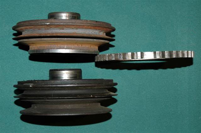
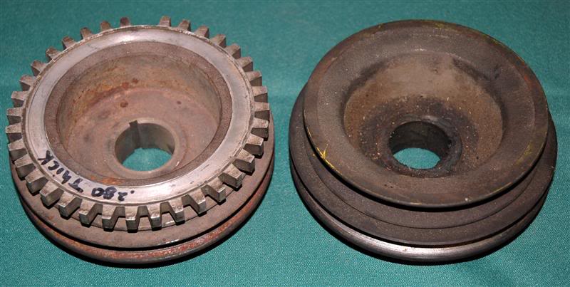
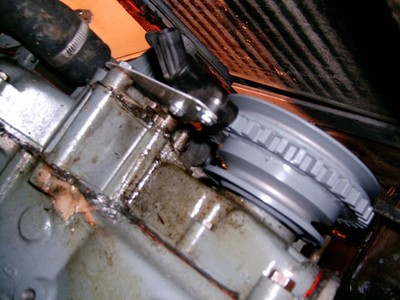
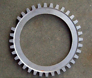
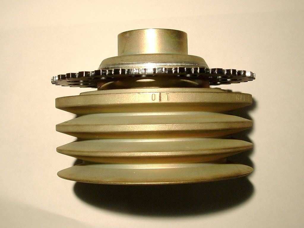
http://datsun1200.com/modules/myalbum/photo.php?lid=25476.

I fitted a Ford trigger wheel to one of these pulleys but getting a fitter mate to turn down the shoulder your talking about to 114mm and removing the front pulley. He then opened the trigger wheel to 114mm, a sliding fit and I epoxied it in position. Epoxy works well if the two metal surfaces are fresh and clean and it's only under inertial load. From memory the Ford wheel was too small to just open up to the shoulder diameter but if you're buying one you could buy a bigger one?

I hope this is helpful, you might find a similar solution works for you.

Posted on: 2016/1/5 23:07
_________________
1200 Coupe A15E - ITB
Lamb Daiquiri - a man's cocktail!
Transfer the post to other applications Transfer


Re: Trigger wheel mount to space in double pulley
Moderator
Joined:
2001/5/3 7:04
From 48 North
Group:
Registered Users
Contentmaster
Usermaster
Posts: 31575
Offline
As long as you create threads equidistant around the circumference, the balance will stay the same. For example, two bolts 180 degrees apart or 3 bolts 120 degrees apart. But why go to all that trouble? The automakers don't weld nor do they bolt the trigger wheel on. They use an interference press fit.

In between the front and rear? Do you mean between the front and rear V-grooves? You could have that lip machined flat and then have a ring pressed on (interference fit). No welding needed -- the ring doesn't drive anything so there is no load on it. An 1/8" thick trigger wheel works fine so there should be enough space for it.

Here's what one guy did for his Datsun engine twin-groove pulley. You could do similar except put it in the middle of the pulley seeing as your pulley has the room.

Attach file:


jpg  Damper1Small.JPG (33.64 KB)
174_568c4d9c1604a.jpg 640X425 px

jpg  Damper3Small.JPG (17.36 KB)
174_568c4dc0a02fd.jpg 640X217 px

jpg  Damper2Medium.JPG (59.49 KB)
174_568c4de3d7d61.jpg 800X403 px

Posted on: 2016/1/5 23:12
Transfer the post to other applications Transfer


Re: Trigger wheel mount to space in double pulley
Moderator
Joined:
2001/5/3 7:04
From 48 North
Group:
Registered Users
Contentmaster
Usermaster
Posts: 31575
Offline
Here's a similar install done to a bimmer pulley. They put the trigger ring between the front and rear V-grooves

Attach file:


jpg  z113872376.jpg (38.05 KB)
174_568c508ec1898.jpg 400X300 px

Posted on: 2016/1/5 23:23
Transfer the post to other applications Transfer


Re: Trigger wheel mount to space in double pulley
Home away from home
Joined:
2009/11/16 1:18
From Sydney, NSW
Group:
Registered Users
Posts: 613
Offline
Thanks guys! That looks awesome!

Who would I take it to to press fit? I'd get the inner diameter the same as the flattened lip? And then get someone to heat and press it on?

Posted on: 2016/1/5 23:32
Transfer the post to other applications Transfer


Re: Trigger wheel mount to space in double pulley
Moderator
Joined:
2001/5/3 7:04
From 48 North
Group:
Registered Users
Contentmaster
Usermaster
Posts: 31575
Offline
You could have a machinist make a trigger ring to the dimensions you want.

The photos above use the USA-spec 1990-1993 Escort ring, which is a press fit on the original Ford car. Only $5 at a wrecking yard or $20 from eBay. At 144 mm, it's the right diameter for the 139mm A12/A14 pulley, and might work for you if machined down to 1/8" thick. This wheel is about 102-103 mm inside diameter.

Attach file:


jpg  edis_escort.jpg (41.34 KB)
174_568c53b47dda6.jpg 322X272 px

Posted on: 2016/1/5 23:37
Transfer the post to other applications Transfer


Re: Trigger wheel mount to space in double pulley
Moderator
Joined:
2001/5/3 7:04
From 48 North
Group:
Registered Users
Contentmaster
Usermaster
Posts: 31575
Offline
Quote:
Who would I take it to to press fit? I'd get the inner diameter the same as the flattened lip? And then get someone to heat and press it on?
You can fit it yourself, after the pulley is machined. Interference fit is something like 1/1000" larger on the shaft than the inside diameter of the ring -- a machinist will know the correct measurement.

One guy said:
Quote:
I made a kit for S14 motors. The trigger wheel only needs to be warmed in the oven, the slid over the pulley. When it is cold there's no way it can be moved.

megasquirt topic
He likes the Ford thin trigger wheel, however that may be too large diameter.
* 1999 Ford F-150 4.6 liter part number F2LE-12A227-BC
* STANDARD MOTOR PRODUCTS part number PC614 "Camshaft Position Sensor Interrupter" $17 USD
* AIRTEX / WELLS 5S6695 $17 USD RockAuto.com

Attach file:


jpg  TriggerWheel_1.jpg (165.93 KB)
174_568c54e2a91e3.jpg 1024X768 px

jpg  TriggerWheel_2.jpg (94.36 KB)
174_568c5514326e1.jpg 1024X768 px

jpg  PC614.jpg (151.02 KB)
174_568c58f73c024.jpg 1024X991 px

Posted on: 2016/1/6 0:04
Transfer the post to other applications Transfer


Re: Trigger wheel mount in Flywheel
Moderator
Joined:
2001/5/3 7:04
From 48 North
Group:
Registered Users
Contentmaster
Usermaster
Posts: 31575
Offline
A more elegant option would be to machine 36 holes in the flywheel, then mount the VR sensor in the back. That's what the factory Zetec engine does. The VR sensor needs 36 "teeth" but they don't need to be in the form of a wheel.

Here's a Zetec (Australia) flywheel. Notice two of the holes are joined to make the "missing" hole. Some Zetecs have square cast holes, while others are machined/drilled.

Attach file:


jpg  zps10329da4.jpg (39.98 KB)
174_568c5e2065f18.jpg 400X300 px

jpg  flywheel.jpg (76.27 KB)
174_568c5ecb904bc.jpg 400X382 px

Posted on: 2016/1/6 0:22
Transfer the post to other applications Transfer


Re: Trigger wheel mount to space in double pulley
Home away from home
Joined:
2009/11/16 1:18
From Sydney, NSW
Group:
Registered Users
Posts: 613
Offline
Haha dd seriously you're waaay too fast! Thanks so much for all the info.. would most ecus work ok with the flywheel mod? sounds like a fun way to go

Posted on: 2016/1/6 0:33
Transfer the post to other applications Transfer


Re: Trigger wheel mount to space in double pulley
Moderator
Joined:
2001/5/3 7:04
From 48 North
Group:
Registered Users
Contentmaster
Usermaster
Posts: 31575
Offline
Yah been thinking about this since 2008. I did the simplest setup back then and it worked flawlessly.

The ECU doesn't know where the signal comes from, so as long as it get a 36-1 signal it will work. The VR sensor likewise doesn't care, as long as it "sees" metal pulses. Same sensor is used for both. That reminds me of when Lucas was pioneering electronic ignition back in 1960 for F1, they used flywheel trigger like this but machined in lots of little magnets (if I remember correctly). They had tremendous problems getting the pulse shape correct. VR Sensor puts the magnet in the sensor, so it's much simpler. All you need is a sharp change and a metal tooth width of about 4 mm.

Here are a variety of VR Sensors used with EDIS, they vary by how they mount and where they point. You can also use GM or Chrysler VR sensors and probably a lot of other brands. Notice the Crown Victoria unit mounts in a hole, with a tab to bolt it down.

Attach file:


jpg  VR_sensors.jpg (14.66 KB)
174_568c6350c52bb.jpg 400X198 px

Posted on: 2016/1/6 0:46
Transfer the post to other applications Transfer


(1) 2 »


You can view topic.
You cannot start a new topic.
You cannot reply to posts.
You cannot edit your posts.
You cannot delete your posts.
You cannot add new polls.
You cannot vote in polls.
You cannot attach files to posts.
You cannot post without approval.

[Advanced Search]