![[Datsun 1200 encyclopedia]](/wiki/upload/wiki.png)
| Revision as of 03:03, 26 July 2011 ddgonzal (Talk | contribs) (->Automatic Choke Relay) <- Previous diff |
Current revision ddgonzal (Talk | contribs) (->Overview) |
||
| Line 1: | Line 1: | ||
| - | Our Datsun B110 used -- as with most 1964-1974 cars -- an [[Alternator]] with external [[Voltage regulator]]. | + | Early 1200 use [[Alternator]] with external [[Voltage regulator]]. Later 1200s (from 1981) use an Internally Regulated (IR) Alternator. |
| = Overview = | = Overview = | ||
| - | '''Alternator Connections''' | + | B110 alternator is 35A and has plastic cover on back |
| - | <table border='1' class='inner' cellspacing='2'> | + | <br>{{Album|24375}} |
| - | <tr bgcolor="ccccff"><td>terminal</td><td>Color</td><td>Logical Connections</td></tr> | + | |
| - | <tr bgcolor=f0f0f0><td>A (Alternator)</td><td>WR or W</td><td>* To Battery + terminal through the [[Fusible Link]]<br>* To Regulator "A" terminal (W wire)</td></tr> | + | 1980s 1200 is still 35A but uses internal regulator (IC REG) |
| - | <tr bgcolor=f0f0f0><td>F (Field)</td><td>WB</td><td>* To Regulator "F" terminal</td></tr> | + | <br>{{Album|24756}} |
| - | <tr bgcolor=f0f0f0><td>N (neutral point)</td><td>Y</td><td>* To Regulator "N" terminal<br>* To electric choke relay Y wire</td></tr> | + | |
| - | <tr bgcolor=f0f0f0><td>E (Earth/ground)</td><td>B</td><td>* To body ground<br>* To Regulator "E" terminal</td></tr> | + | Both use the same T-connector, but IC REG alternator socket is additionally notched |
| + | <br>{{PhotoTh!|LRplug.jpg}} {{PhotoTh!|FNplug.jpg}} | ||
| + | |||
| + | Datsun used the simple T-connector, but the NipponDenso C900 style can also be used. The locking tab prevents the connector from falling out. | ||
| + | <br>{{Photo2|C900.jpg}} | ||
| + | |||
| + | = Early 1200 = | ||
| + | Our Datsun B110 used -- as with most 1964-1974 cars -- an [[Alternator]] with external [[Voltage regulator]]. | ||
| + | |||
| + | {{Album|25445}} | ||
| + | |||
| + | '''Alternator Connections'''<table class="wiki_table" style="width:600px;"> | ||
| + | <tr><th>terminal</th><th>Color</th><th>Logical Connections</th></tr> | ||
| + | <tr><td>A (Alternator)</td><td>W</td><td>* To Battery + terminal through the [[Fusible Link]]<br>* To Regulator "A" terminal (W wire)</td></tr> | ||
| + | <tr><td>F (Field)</td><td>WB</td><td>* To Regulator "F" terminal</td></tr> | ||
| + | <tr><td>N (neutral point)</td><td>Y</td><td>* To Regulator "N" terminal<br>* To electric choke relay Y wire</td></tr> | ||
| + | <tr><td>E (Earth/ground)</td><td>B</td><td>* To body ground<br>* To Regulator "E" terminal</td></tr> | ||
| </table> | </table> | ||
| + | Alternator uses the typical 1970s T-shaped connector: | ||
| + | F Field - stem of Tee | ||
| + | N Neutral point - head of Tee | ||
| - | '''Regulator Connections''' | + | '''Regulator Connections'''<table class="wiki_table" style="width:600px;"> |
| - | <table border='1' class='inner' cellspacing='2'> | + | <tr><th>terminal</th><th>Color</th><th>Logical Connections</th></tr> |
| - | <tr bgcolor="ccccff"><td>terminal</td><td>Color</td><td>Logical Connections</td></tr> | + | <tr><td>A (Alternator)</td><td>W</td><td>* To Alternator "A" terminal (W)</td></tr> |
| - | <tr bgcolor=f0f0f0><td>A (Alternator)</td><td>W</td><td>* To Alternator "A" terminal (WR or W)</td></tr> | + | <tr><td>F (Field)</td><td>WB</td><td>* To Alternator "F" terminal</td></tr> |
| - | <tr bgcolor=f0f0f0><td>F (Field)</td><td>WB</td><td>* To Alternator "F" terminal</td></tr> | + | <tr><td>N (neutral point)</td><td>Y</td><td>* To Alternator "N" terminal<br>* To electric choke relay Y wire</td></tr> |
| - | <tr bgcolor=f0f0f0><td>N (nuetral point)</td><td>Y</td><td>* To Alternator "N" terminal<br>* To electric choke relay Y wire</td></tr> | + | <tr><td>E (Earth)</td><td>B</td><td>* To body ground<br>* To Alternator "E" terminal</td></tr> |
| - | <tr bgcolor=f0f0f0><td>E (Earth)</td><td>B</td><td>* To body ground<br>* To Alternator "E" terminal</td></tr> | + | <tr bgcolor=f0f0f0><td>IG (ignition)</td><td>WL</td><td>* To fuse box "M" terminal (does not go through IGN switch)</td></tr> |
| - | <tr bgcolor=f0f0f0><td>IG (ignition)</td><td>WL (72: W?)</td><td>* To fuse box "M" terminal (does not go through IGN switch)</td></tr> | + | <tr><td>L (Light)</td><td>WR</td><td>* To dash light "IGN" ('72, '73) or "CHG" (1971)</td></tr> |
| - | <tr bgcolor=f0f0f0><td>L (Light)</td><td>WR</td><td>* To dash light "IGN" ('72, '73) or "CHG" (1971)</td></tr> | + | |
| </table> | </table> | ||
| + | Voltage Regulator Pinout | ||
| + | <br>{{Photo!|1V1250_pinout.jpg|Datsun%201200/Parts2|width=SM}} | ||
| + | Wire Color | ||
| + | WR Lamp (to dash lamp) | ||
| + | W Positive (12V from Fusible Link) | ||
| + | Y Stator (Neutral point, tee-connector N) | ||
| + | B Ground (Earth to horn bracket) | ||
| + | WB Field (Tee-connector F) | ||
| + | WL Ignition ([[Fuse Box|'M' fuse]]) | ||
| - | = How the Alternator Dash Light Works = | + | = Late-model Alternator = |
| - | The dash lamp is connected to IGN +. The other side goes to the "L" terminal of the external regulator. | + | Datsun 1200 from 1981 (Japan-market models) use an internally-regulated Hitachi [[Hitachi LR Alternator|LR Alternator]] or equivalent. The LR135 has LS wiring like many modern Japanese alternators. The L-terminal goes to the CHG lamp, and the S-terminal goes to either IGN or straight to the battery. |
| - | * When the alternator is not putting out current, the "L" terminal is at '-' voltage, so the dash light turns on | + | |
| - | * Once the alternator starts putting out current, the "L" terminal is at + voltage, so the light turns off (both sides of the light are at +) | + | |
| + | {{Album|24517}} | ||
| - | This also is connected to the F (field) connection of the alternator, so it "turns on" the alternator. It is the switched 12V (through the lamp) that kick starts the alternator fields. | + | {{Album|24374}} |
| - | WARNING: This mean that if the dash lamp | + | == Using in Older 1200 == |
| - | is burned out, the alternator does not work | + | The LR135 is a bolt-in replacement for the LT135 BUT you must modify the wiring slightly. |
| - | = Automatic Choke Relay = | + | See main article: [[IR Alternator Conversion Wiring]] |
| - | On Datsuns equipped with an electric [[Automatic Choke]], a relay is used so that the choke heater is activated only when the engine is running. As soon as the choke heats up, it comes off the choke. If your engine is cold, you won't be able to restart it. For example, if you listen to the radio for a couple of minutes before starting the engine, and mistakenly put it to IGN, then the car won't start on a cold day. | + | |
| - | To prevent this scenario, the relay only powers the choke when the engine is running. The alternator provides a signal when the engine is running. It is the Neutral Sense wire (N wire). This is a weak signal so a relay is used. | + | = Engine Swaps = |
| + | See main article: [[Basic Alternator Wiring]] | ||
| - | The choke is powered by a separate 10A fuse, which also supplies the [[Anti-Dieseling Valve]]. | + | = How the Alternator Dash Light Works = |
| + | The dash lamp is connected to IGN +. The other side goes to the "L" terminal of either the external regulator or alternator. A relay turns the dash lamp on/off. | ||
| - | The relay is connected to Ground on one side, and to the N wire on the other. | + | * When the alternator is not putting out current, the "L" terminal is at ground/earth, so the dash light turns on |
| + | * Once the alternator starts putting out current, the "L" terminal is at full voltage, so the light turns off (both sides of the light are at same voltage) | ||
| - | Black: ground | + | <blockquote>WARNING: If the dash lamp is burned out, the alternator does not work. The lamp circuit is used to start the alternator.</blockquote> |
| - | L (Blue): to 10A fuse then to IGN FUSE BOX (always hot) | + | |
| - | Red: choke | + | |
| - | Yellow: N wire of alternator & regulator (turns on relay) | + | |
| + | == External Regulator == | ||
| + | The dash lamp is connected to IGN +. The other side goes to the "L" terminal of the external regulator. A relay inside the [[Voltage Regulator]] turns the dash lamp on/off. | ||
| - | Note that other Datsuns may be wired just the opposite. | + | * When the alternator is not putting out current, the "L" terminal is at '-' voltage, so the dash light turns on |
| - | <br>[http://datsun1200.com/modules/myalbum/photo.php?lid=23479 http://datsun1200.com/uploads/thumbs/23479.jpg] | + | * Once the alternator starts putting out current, the "L" terminal is at + voltage, so the light turns off (both sides of the light are at +) |
| - | = Alternator Upgrade = | + | This also is connected to the F (field) connection of the alternator, so it "turns on" the alternator. It is the switched 12V (through the lamp) that kick starts the alternator fields. |
| - | Many different Datsun alternators and alternators from other makes can easily be fitted to the Datsun 1200. | + | |
| + | == Internal Regulator == | ||
| + | Internally regulated Hitachi LR alternators (S-L type) use the L terminal to turn the dash lamp on and off, using a transistorized switch inside the alternator. | ||
| + | |||
| + | = Automatic Choke Relay = | ||
| + | On Datsuns equipped with an electric [[Automatic Choke]], a relay is used so that the choke heater is activated only when the engine is running. | ||
| - | See main article: [[Alternator Upgrades]] | + | See main article: [[Electric Choke Wiring]] |
| + | {{End}}[[Category:Charging System]][[Category:Wiring]] | ||
Current revision
Early 1200 use Alternator with external Voltage regulator. Later 1200s (from 1981) use an Internally Regulated (IR) Alternator.
Contents |
Overview
B110 alternator is 35A and has plastic cover on back
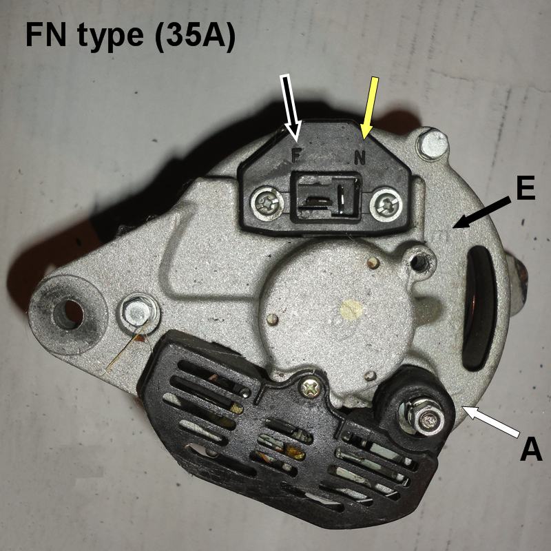
1980s 1200 is still 35A but uses internal regulator (IC REG)
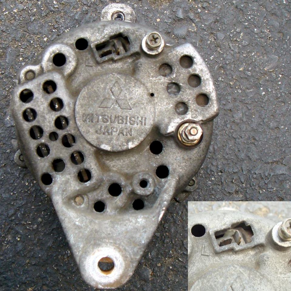
Both use the same T-connector, but IC REG alternator socket is additionally notched


Datsun used the simple T-connector, but the NipponDenso C900 style can also be used. The locking tab prevents the connector from falling out.

Early 1200
Our Datsun B110 used -- as with most 1964-1974 cars -- an Alternator with external Voltage regulator.

| terminal | Color | Logical Connections |
|---|---|---|
| A (Alternator) | W | * To Battery + terminal through the Fusible Link * To Regulator "A" terminal (W wire) |
| F (Field) | WB | * To Regulator "F" terminal |
| N (neutral point) | Y | * To Regulator "N" terminal * To electric choke relay Y wire |
| E (Earth/ground) | B | * To body ground * To Regulator "E" terminal |
Alternator uses the typical 1970s T-shaped connector:
F Field - stem of Tee
N Neutral point - head of Tee
Regulator Connections
| terminal | Color | Logical Connections |
|---|---|---|
| A (Alternator) | W | * To Alternator "A" terminal (W) |
| F (Field) | WB | * To Alternator "F" terminal |
| N (neutral point) | Y | * To Alternator "N" terminal * To electric choke relay Y wire |
| E (Earth) | B | * To body ground * To Alternator "E" terminal |
| IG (ignition) | WL | * To fuse box "M" terminal (does not go through IGN switch) |
| L (Light) | WR | * To dash light "IGN" ('72, '73) or "CHG" (1971) |
Voltage Regulator Pinout
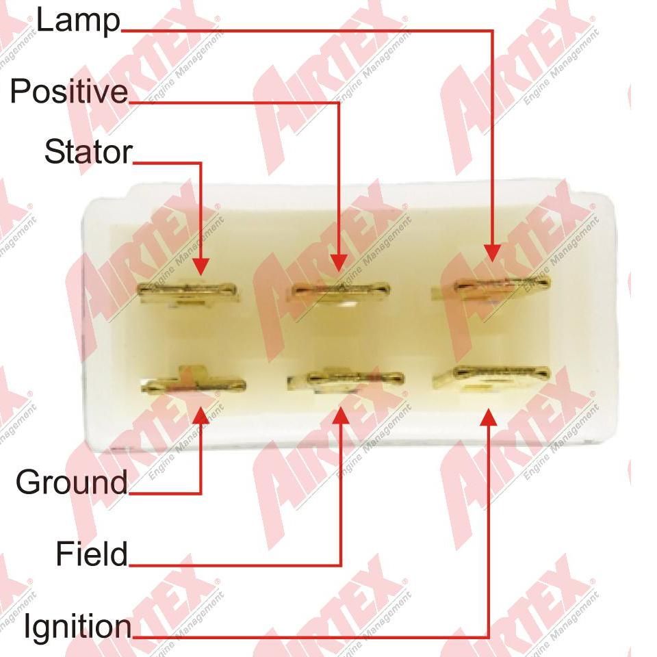
Wire Color
WR Lamp (to dash lamp)
 W Positive (12V from Fusible Link)
 Y Stator (Neutral point, tee-connector N)
 B Ground (Earth to horn bracket)
WB Field (Tee-connector F)
WL Ignition ('M' fuse)
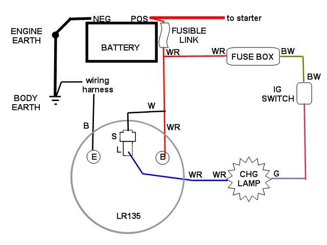
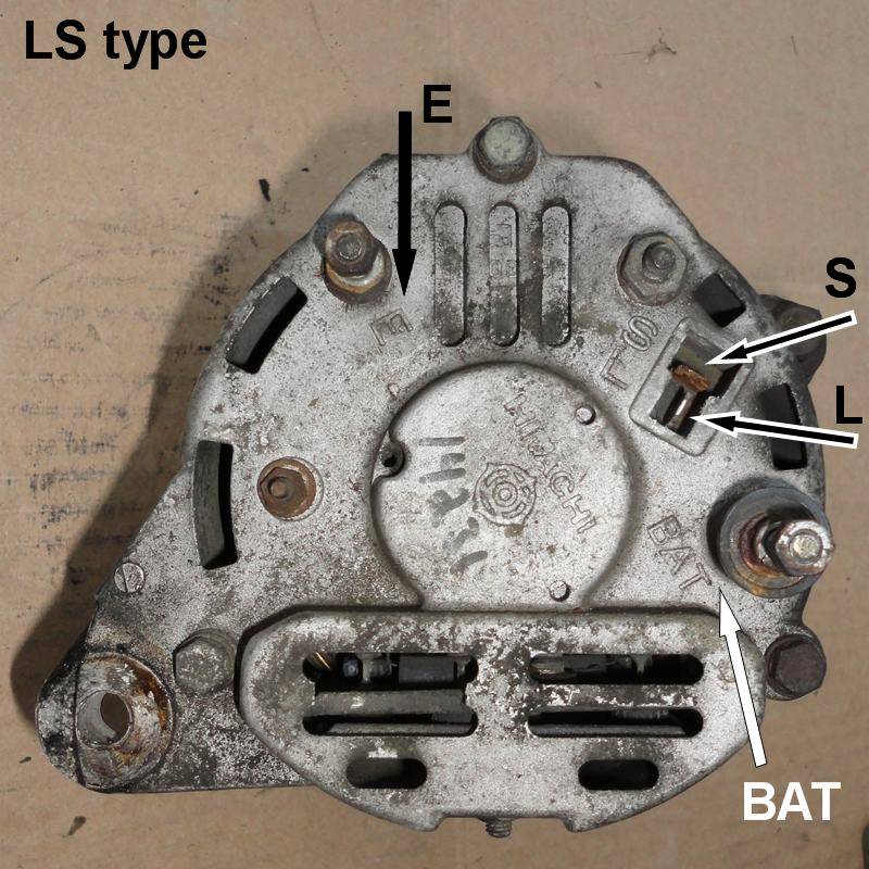
Late-model Alternator
Datsun 1200 from 1981 (Japan-market models) use an internally-regulated Hitachi LR Alternator or equivalent. The LR135 has LS wiring like many modern Japanese alternators. The L-terminal goes to the CHG lamp, and the S-terminal goes to either IGN or straight to the battery.
Using in Older 1200
The LR135 is a bolt-in replacement for the LT135 BUT you must modify the wiring slightly.
See main article: IR Alternator Conversion Wiring
Engine Swaps
See main article: Basic Alternator Wiring
How the Alternator Dash Light Works
The dash lamp is connected to IGN +. The other side goes to the "L" terminal of either the external regulator or alternator. A relay turns the dash lamp on/off.
- When the alternator is not putting out current, the "L" terminal is at ground/earth, so the dash light turns on
- Once the alternator starts putting out current, the "L" terminal is at full voltage, so the light turns off (both sides of the light are at same voltage)
WARNING: If the dash lamp is burned out, the alternator does not work. The lamp circuit is used to start the alternator.
External Regulator
The dash lamp is connected to IGN +. The other side goes to the "L" terminal of the external regulator. A relay inside the Voltage Regulator turns the dash lamp on/off.
- When the alternator is not putting out current, the "L" terminal is at '-' voltage, so the dash light turns on
- Once the alternator starts putting out current, the "L" terminal is at + voltage, so the light turns off (both sides of the light are at +)
This also is connected to the F (field) connection of the alternator, so it "turns on" the alternator. It is the switched 12V (through the lamp) that kick starts the alternator fields.
Internal Regulator
Internally regulated Hitachi LR alternators (S-L type) use the L terminal to turn the dash lamp on and off, using a transistorized switch inside the alternator.
Automatic Choke Relay
On Datsuns equipped with an electric Automatic Choke, a relay is used so that the choke heater is activated only when the engine is running.
See main article: Electric Choke Wiring