| Revision as of 06:31, 31 October 2023 ddgonzal (Talk | contribs) (->Connects To) <- Previous diff |
Revision as of 07:31, 1 November 2023 ddgonzal (Talk | contribs) (*/ B210 /*) Next diff -> |
||
| Line 1: | Line 1: | ||
| - | TS/Beam Switch Assembly (dimmer switch, flicker switch) is a key part of the [[Turn Signals]] system. | + | TS/Beam Switch Assembly (column-mounted stalk dimmer switch/flicker switch) is a key part of the [[Turn Signals]] system. |
| = Connects To = | = Connects To = | ||
| Line 33: | Line 33: | ||
| {{Album|19662}} {{Album|19663}} {{Album|23135}} {{Album|23136}} | {{Album|19662}} {{Album|19663}} {{Album|23135}} {{Album|23136}} | ||
| + | |||
| + | = B210 = | ||
| + | The B210 indicator/high-beam switch has differences from the 1200 switch, it has the same 4-pin large connector but it has a 2nd square wire connector instead of the three individual wires. It looks very close and fastens to the column same way with two bolts, however it is unknown if it will bolt up to the 1200 column. | ||
| + | |||
| + | {{UploadPost|174_6541cfbe036f1.jpg|498012}} | ||
| + | |||
| + | 25540-H5000 with large connector having 4 or 6 pins | ||
| + | 25540-H5010 7624A 4-pin large connector | ||
| + | 25540-H5300 superceeds H5000 | ||
| + | |||
| + | B210 electrical connectors differ (small square connector instead of three individual wires) | ||
| + | <br>{{UploadPost|174_6541d041469ea.jpg|498012}} | ||
| + | |||
| + | The Horn ring contact arm is facing the opposite direction compare to the 1200 | ||
| + | <br>{{UploadPost|174_6541d09712710.jpg|498012}} | ||
| + | |||
| + | The two clamping screws are facing the opposite direction compared to the 1200 swith | ||
| + | <br>{{UploadPost|174_6541d02a67834.jpg|498012}} | ||
| + | |||
| + | {{UploadPost|174_6541d05024d56.jpg|498012}} | ||
| ディマースイッチ ウィンカースイッチ | ディマースイッチ ウィンカースイッチ | ||
| [[Category:Body Electrical System]]{{End}} | [[Category:Body Electrical System]]{{End}} | ||
Revision as of 07:31, 1 November 2023
TS/Beam Switch Assembly (column-mounted stalk dimmer switch/flicker switch) is a key part of the Turn Signals system.
Connects To
The turn signal switch connects to:
- Steering Column
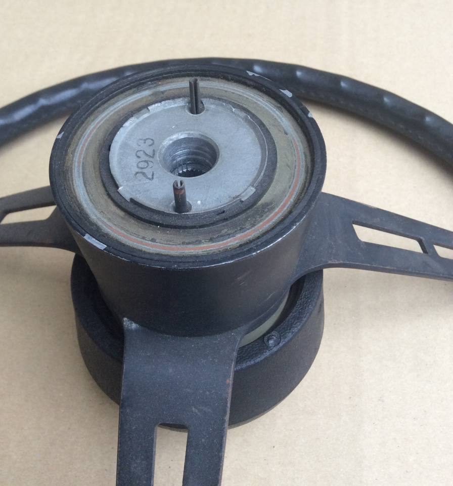
- Steering wheel. Specifically the pins on the bottom of the steering wheel hub cancel the turn signals when the wheel is turned
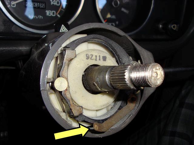
- Horn pad on the steering wheel, via the copper spring-action contact
-
Overview
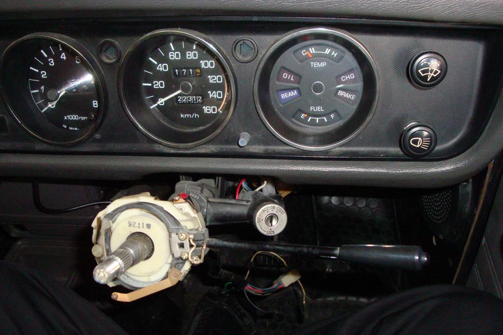
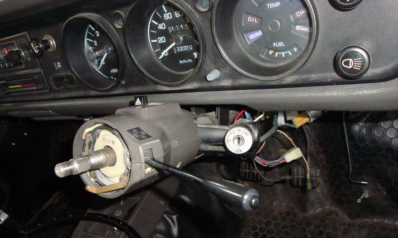
The TS/Beam Switch mounts on the Steering Column, just behind the Steering wheel. It contains the turn signal lever stalk, cancelling mechanism and the Horn contact wiring.
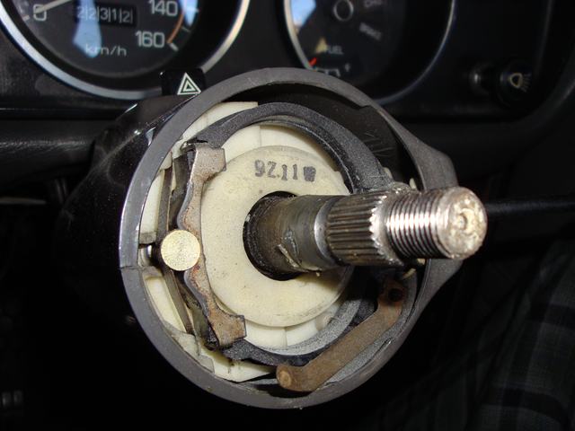
Steering wheel cancelling pins
Standard switch
SWITCH COMP-turn signal & dimmer
25540-H1007  B110 STD, B120 -7803 $155.78 USD
* superceded 25540-H1006
25540-H1007L B120 (BENT ARM 10 DEGREE)
25540-HG007  B120 (STRAIGHT ARM)
passing switch type
25540-H1100 SWITCH COMP-turn signal & dimmer
* OPTION DX, GL, GX
* Optional on B120 -7803
* Standard on B120 7804-
RHD & LHD use the same T/S switch assembly. Just rotate it 180 degrees.
B210
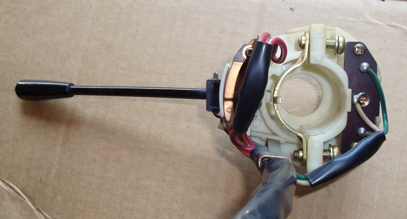
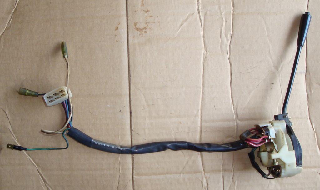
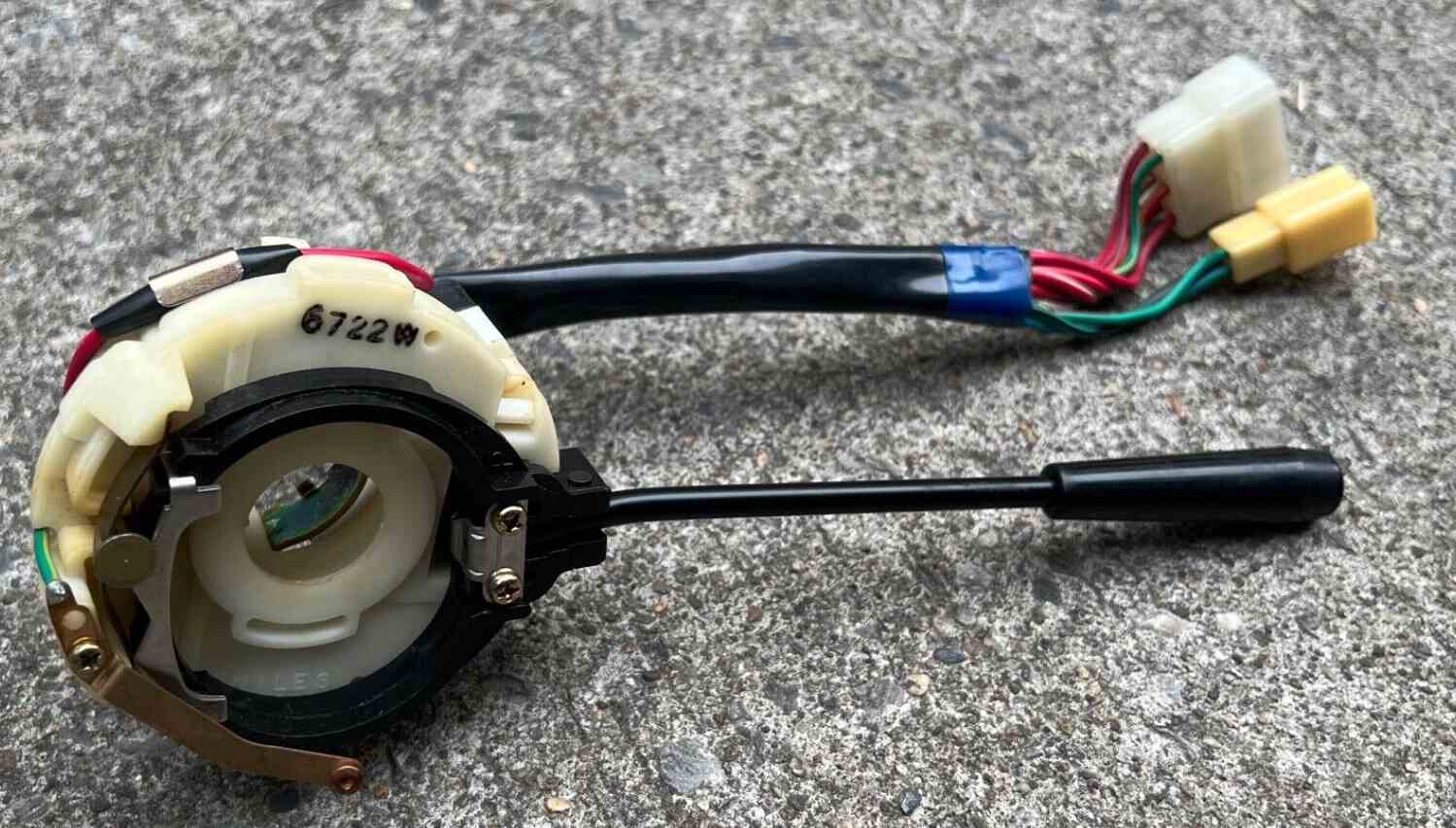
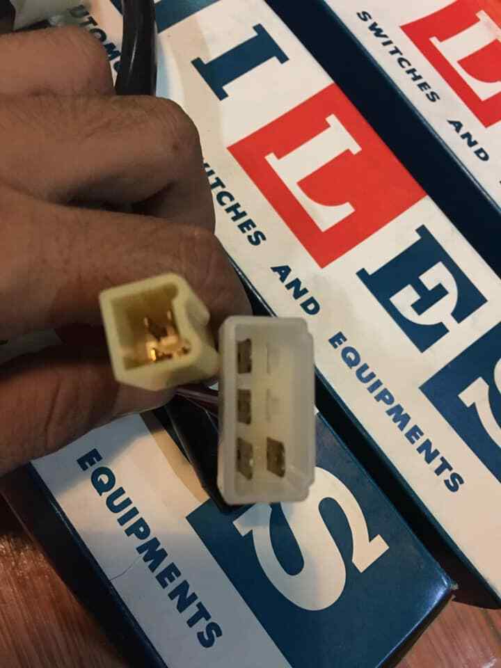
The B210 indicator/high-beam switch has differences from the 1200 switch, it has the same 4-pin large connector but it has a 2nd square wire connector instead of the three individual wires. It looks very close and fastens to the column same way with two bolts, however it is unknown if it will bolt up to the 1200 column.
25540-H5000 with large connector having 4 or 6 pins
25540-H5010 7624A 4-pin large connector
25540-H5300 superceeds H5000
B210 electrical connectors differ (small square connector instead of three individual wires)
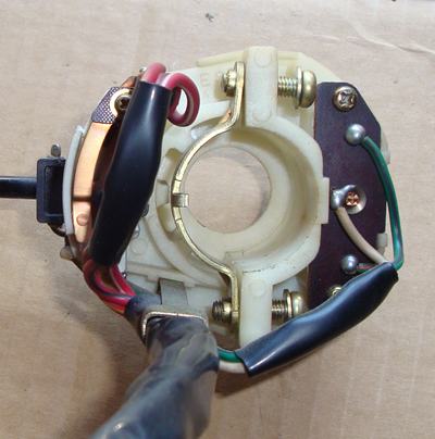
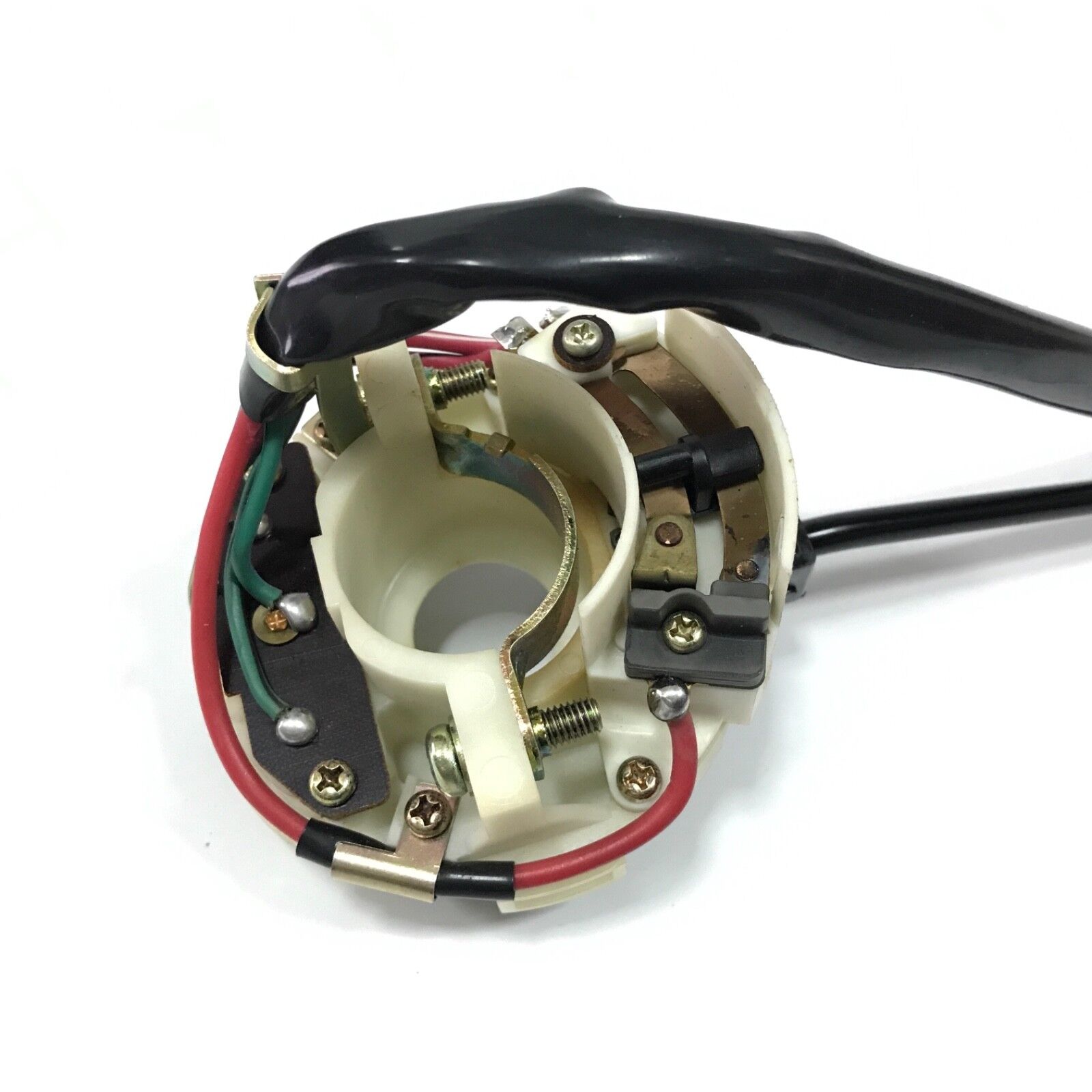
The Horn ring contact arm is facing the opposite direction compare to the 1200

The two clamping screws are facing the opposite direction compared to the 1200 swith
ディマースイッチ ウィンカースイッチ

![[Datsun 1200 encyclopedia]](/wiki/upload/wiki.png)
