In 1977 Nissan released the B310 and three months introduced new trims GX-E and SGX-E. These featured fuel injected (EGI) engines, the legendary A14E motor. It improved upon the B310 GX which came with a single carburetor A14S motor. Nissan "introduction" Service Bulletin Number 350 highlights the features of the new model, in this case the biggest change from the GX to the GX-E is the Fuel Injection system. The Service Bulletin No. 350 is 60 pages.
PART 1 (Specifications, Engine) | PART 2 (Chassis, Body)
|
 |
Overview
cover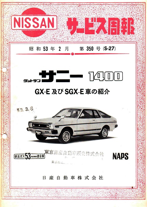 | NISSAN サービス周報
NISSAN Service Bulletin 昭 和 53 年 2月 第 350 号 (S-27) February 1978 No. 350 (S-27) |
ダットサンサンー1400 GX-E皮び SGX-E車の紹介
Introduction of Datsun Sunny 1400 GX-E SGX-E Models
排出ガス 53 年度規制適合車 NAPS
Exhaust Gas 1978 Fiscal Year Automobile Compliance [Nissan Anti-Pollution System]
日産自動車株式会社 Nissan Motor Co., Ltd.
はじめに Introduction
Page 1 Page 28 PDF

Page 2 Page 39 PDF
 full
full
 full
full
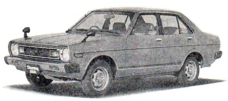
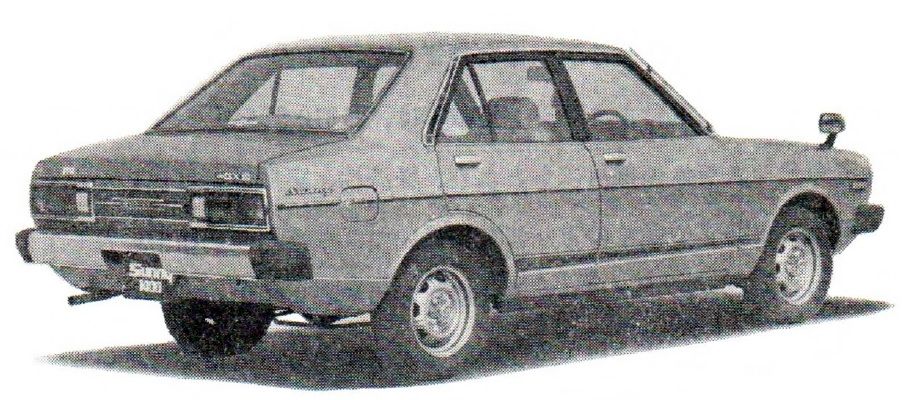
Sunny 1400 4-door Sedan GX-E サニー 1400 4 ドア セダン GX-E
 full
full
 full
full
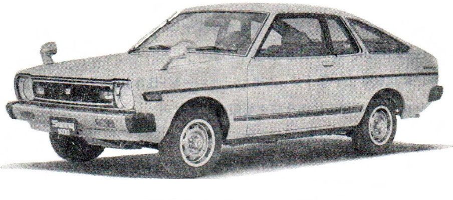
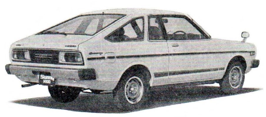
Sunny 1400 Coupe SGX-E サニー 1400 クーペ SGX-E
Page 3 Page 50 PDF
 full
full
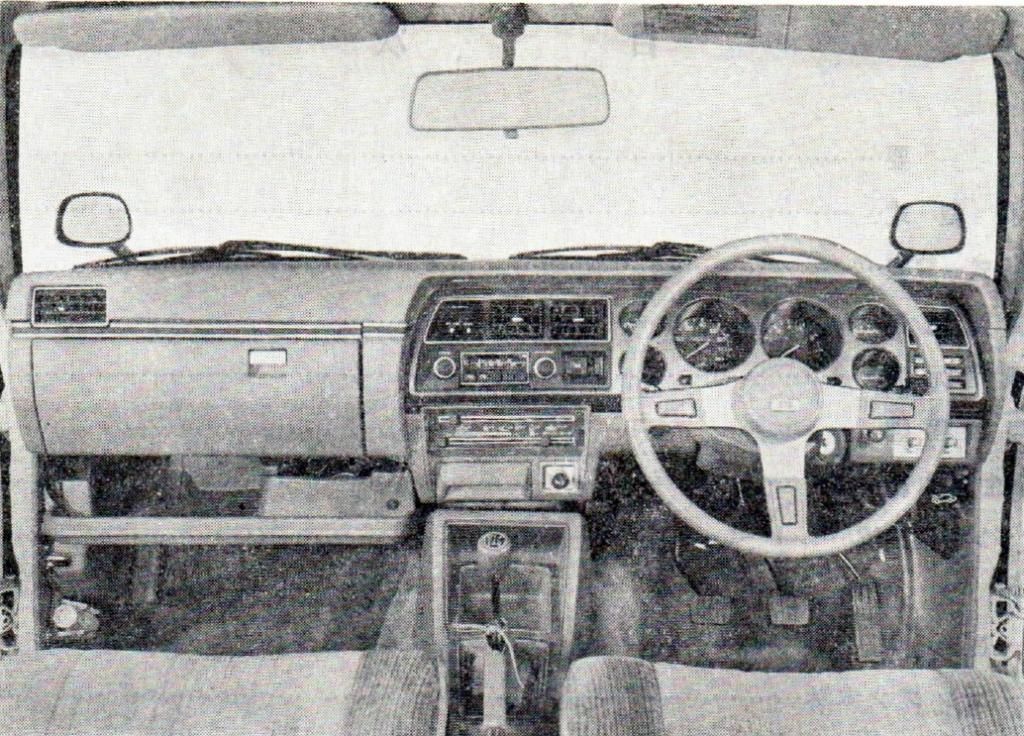
Sunny 1400 Coupe SGX-E Instruments サニー 1400 クーペ SGX-E インストルメント
 full
full
A14-type EGI-specification Engine A14型 EGIエンジン仕様
目次 Table of Contents
Page 4 Page 2 PDF

Summary
概要 Summary
Page 5 Page 4 PDF

92PS/6,400rpm A14 engine with electronic controlled fuel injection (EGI)
プロペラ シャフトの2分割3ジョエント方式
2 division, 3 u-joint formula Propeller Shaft
Accent Stripe & Rear Emblem
車台実施始番号
CHASSIS NUMBERS
E-HB310型車 Vehicle Types
HB310-000001〜250000(日産車体)セダン        (Nissan car body) sedan
HB310-250001〜500000(冨士重工)クーペ        (Fuji Heavy Industries) coupe
HB310-500001〜999999(座間工場)セダン、クーペ (Zama plant) sedan, coupe
[page 6 original page 5 PDF]
車種構 成 Model Configuration
4-door GX-E  4-speed, 5-speed
       SGX-E 4-speed, 5-speed
Coupe  GX-E  4-speed, 5-speed
       SGX-E 4-speed, 5-speed
Model Type
車種型式 Model Type
Page 7 Page 6 PDF

--Model--     -頬別--
E - HB310     KRHEAZ
    H: 1400cc      Z: for Okinawa
                   -: Other
    -: 1200cc     A: automatic transmission
                  F: 5-speed transmission
                  -: 4-speed transmission
                 E: EGI-spec engine
                 -: Carburetor-spec engine
                S: CT [city]
                D: Deluxe
                H: GL, SGL
                X: GX, SGX
               R: 2-door
               -: 4-door
              K: coupe
              -: sedan
E: 1978 emissions regulations
Coupe KHB310
base is Deluxe
LA= SGL,SGX
Z= Cold weather model
O= For Okinawa
Model Table
車種型式ー覧表 Model Type - Table List
Page 9 Page 8 PDF

Page 10 Page 9 PDF

Main Specifications Table
主要諸元表 Main Specifications Table
Page 11 Page 10 PDF
 |
車名及び型式 ダットサン E-HB310 道 称 名 4 ドア クーペ
XE KXE
mm 3995
幅 mm 1590 1595
轴 距 mm 2340
|
 Main Specifications Table

Car name and model    Datsun E-HB310
Trim                 four-door  coupe
                     XE         KXE
          mm             3995
Width     mm         1590       1595
Wheelbase mm             2340
|
Specification Table
明細諸元表 Specification Table
Page 12 Page 11 PDF

Page 13 Page 12 PDF

Page 14 Page 13 PDF

Page 15 Page 14 PDF

Page 16 Page 15 PDF

Page 17 Page 16 PDF

Appearance
外観四面図 Appearance All-sides Diagrams
Page 18 Page 17 PDF

Page 19 Page 18 PDF

Driving Performance Curve
走行性能曲線 Driving Performance Curve
Page 20 Page 19 PDF

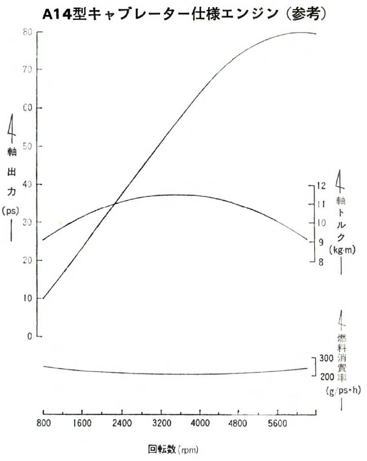
Engine Performance Curve
エンジン 性能 曲線 Engine Performance Curve
Page 21 Page 21 PDF

Horsepower
A14 : 80 PS @ 6000 RPM
A14E: 92 PS @ 6400 RPM
NOTE: Pferdestärke (PS), abbreviation of the German term for metric horsepower, almost exactly the same as SAE Horsepower.
Torque:
A14 : 11.5 kg/m @ 3600 RPM
A14E: 11.7 kg/m @ 3600 RPM
A14型 EGIエンジン仕様
A14-type EGI-specification Engine
 full
full
A14型 キャブレーターエンジン仕様
A14-type Carburetor-specification Engine
 full
full
Engine
1. Summary
Page 22 Page 22 PDF

1.1 Summary
E-HB310 type vehicle, certified for 1978 emissions, A14 with EGI engine
E-HB310  A14  meets 1978 emissions standards
E-HB310  A14E meets 1978 emissions standards
E-B310   A12A meets 1978 emissions standards
H-VHB310 A12  meets 1975 emissions standards
Page 23 Page 23 PDF

Engine Number Embossing 番号打刻
A14-121716P~
1.3 Engine something
Page 24 Page 24 PDF

1.4 NAPS specification
Page 25 Page 25 PDF

Engine Room
1.5
Page 26 Page 26 PDF

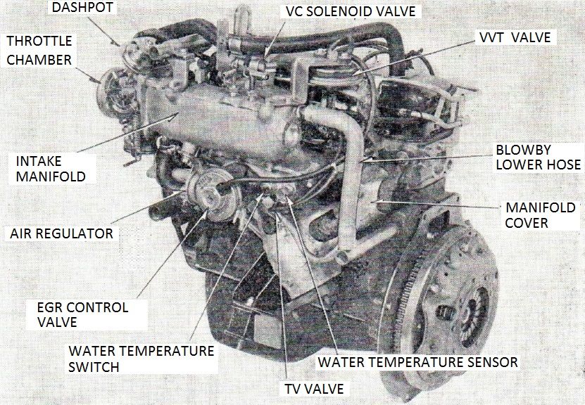
Engine Appearance
1.6 Engine 外観 Appearance
Page 27 Page 27 PDF

Left side of engine
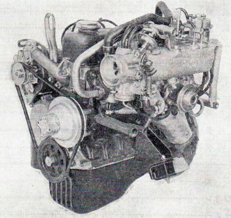
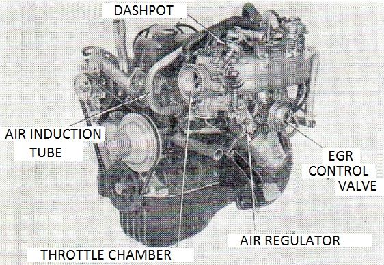 full | original
Right side of engine
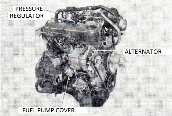 full | original
EGI Control System
1.7 A-series EGI-specification engine Control System
Page 28 Page 29 PDF

Engine something
1.8 Engine
Page 29 Page 30 PDF

Page 30 Page 31 PDF

Basic Engine
2. エンジン本体 Basic Engine
Page 31 Page 32 PDF

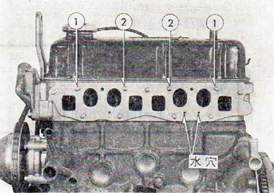
Intake Manifold Stud Length
1  45mm length
2  40mm length
   28mm length (additional studs)
水穴 water holes
Piston
2.2 Piston
No. 1-4 "E"
Camshaft
Cam taken from B-HB211 (A14 Twin Carburetor)
Timing
A14E: 20, 56, 58, 18
A14:  14, 54, 56, 20
Valve Spring and Valve Seat
Page 32 Page 33 PDF

Same as B-HB211 (A14 Twin Carburetor)
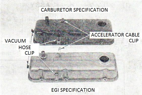
Rocker Cover Assembly
2.5
A14E: Gold Top
A14S: Blue Top
 full | original
キャブレーターエンジン仕様 Carburetor specification
EGI仕様 EGI specification
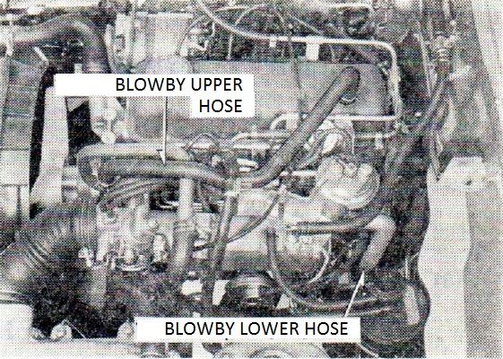
Blowby Hose ASSY
2.6 PCV Positive Crankcase Ventilation System
Manifold
2.2 Manifold
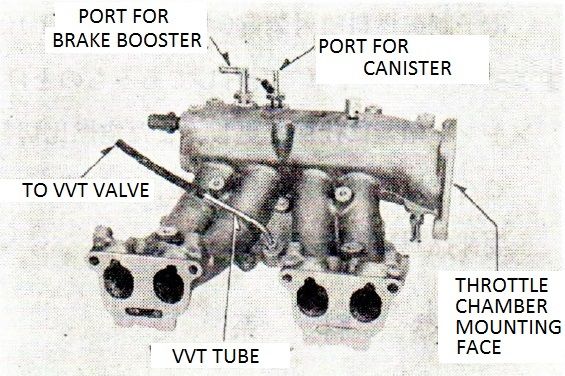
Intake Manifold
2.2.1
Page 33 Page 34 PDF

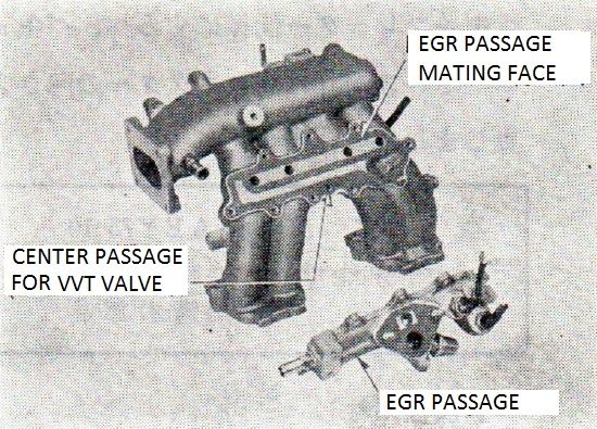
負圧取り出し Negative pressure taken out
VVT バルブへ To the VVT Valve
Exhaust Manifold
2.2.2
Manifold Cover
2.2.3
Intake Manifold Gasket
2.2.4
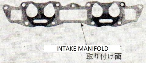 original
取り付け面 clamp face
See 14035-H9202
Intake Manifold Bracket
2.2.5
= Electronic Fuel Injection
3. 電子制御料噴射装置 Electronic Control Fuel Injection (Nissan EGI)
Page 34 Page 35 PDF

B-PA10 (L16 engine) [Stanza]
B-S11 (L18 engine) [S10 Silvia]
Fuel System
3-1 燃料系
Fuel Pump, Fuel Damper
3.1.1 Fuel Pump, Fuel Damper
Fuel Filter
3.1.2 Fuel Filter
Fuel Tube
3.1.3 Fuel Tube
Fuel Injector
3.1.4 Fuel Injector
Pressure Regulator
3.1.5 Pressure Regulator
Air System
3.2 空気系
Page 35 Page 36 PDF

Air Duct
3.2.1 Air Duct
Air Cleaner Element
3.2.2 Air Cleaner Element
Air Flow Meter
3.2.3 Air flow meter
B-HB310 A31-000400 22680-H9200
B-PA10  A31-000310 22680-W5501
B-S11   A31-000121 22680-N6904
Air Duct Hose
エア ダクト ホース
3.2.4 Air duct hose
air flow meter 60mm
throttle chamber 77mm
Throttle Chamber
3.2.5 Throttle Chamber
Page 36 Page 37 PDF

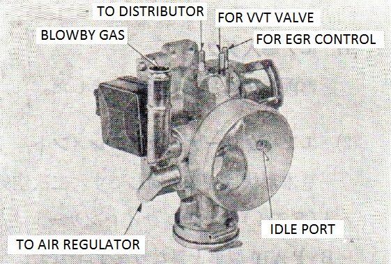
Air Regulator port
Blowby Gas (PCV) port
Idle port
EGR port
VVT port
Distributor Vacuum port
Air Regulator
3.2.6 Air Regulator
???
車種 car model
流量 flow rate
識別 identification
項目 item
| B-PA10 | |||
| B-HB310 | B-S11 | ||
| 20°C flow rate | 14m³/h | 19m³/h | |
| identification | A32-000400 | - |
Electronic Control System
3.3 電子制御系
Page 37 Page 38 PDF

Control Unit
3.3.1 Control Unit
Fuel Increase Correction
3.3.2 燃料増量補正
Page 39 Page 41 PDF

Air-fuel ratio switching instrumentation
3.4 空燃比切替装
Page 40 Page 42 PDF

EFI Relays
3.5 電子制御燃料噴射装?のリレー類
Page 41 Page 43 PDF

3.5.1 EGI Relay
3.5.2 Fuel Pump Relay
EGR
4. 排気 ガス還流(EGR)装置
4. Exhaust Gas Recirculation (EGR) Equipment
Page 42 Page 44 PDF

EGR Equipment
4-1 排気ガス還流装置の装置;
4-1 EGR Equipment
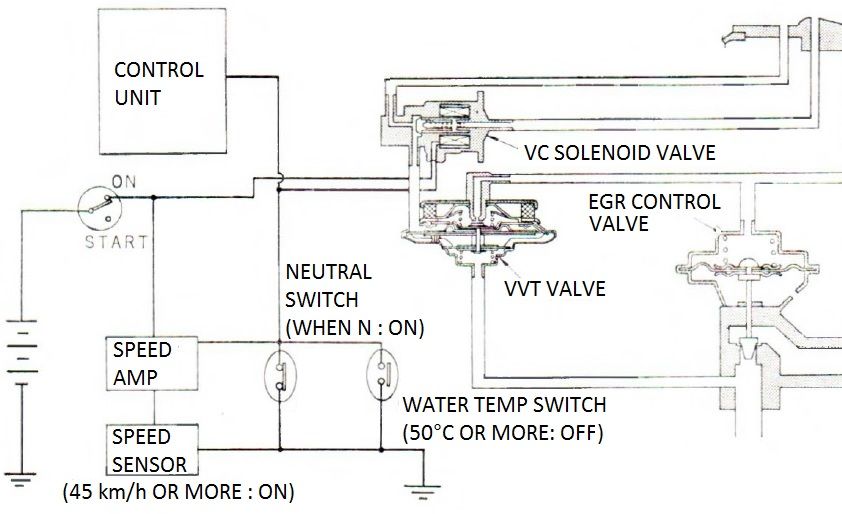
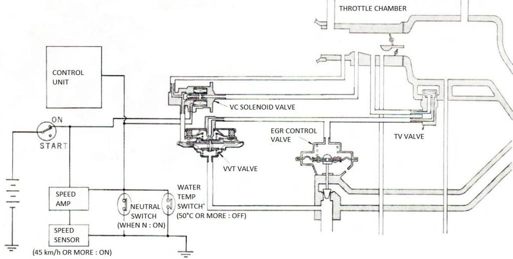
EGR装置は、キャブレター仕様と同じ負荷比例代です。制御信号として排圧のほかに吸入空気量(負荷)に比するベンチュリー負圧を加する
COMPONENT PARTS
  PART NAME                FUNCTION
1 neutral switch           neutral position detection
2 speed sensor, speed amp  detection vehicle speed from about 45 km/h
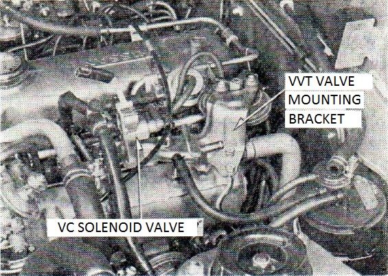
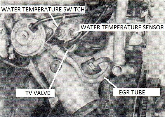
3 TV valve                 water temp (about 50C) ???
4 VC solenoid valve        ?
5 VVT valve                ?
6 EGR control valve        ?
Page 43 Page 45 PDF

WATER TEMP         TRANSMISSION   VEHICLE         VC solenoid  VENTURI
(TV VALVE)         GEAR POSITION  SPEED           valve
about 50C or less  -              -               -
about 50C or more  neutral        -               ON
                   except neutral ~45km/h or less OFF
                                  ~45km/h or more ON
EGR 2
4-2 排気ガス還流装置の概要
4-2 Overview of the Exhaust Gas Recirculation system
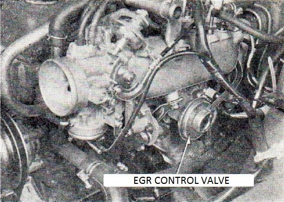
EGR Control Valve
4.2.1 EGR Control Valve
VVT Tube
4.2.2 VVT Tube
VVT Valve Bracket
4.2.3 VVT Valve Bracket
Page 44 Page 46 PDF

取り付け mounting
EGR Passage
4.2.4 EGR Passage
排気ガス涌 路
Straight Connector
4.2.5 Straight Connector
互換性:なし(A12A型、キャブレター仕様と有)
Compatibility: None (A12A type, carburetor specifications and ?)
EGR Tube
4.2.6
水温 water temperature
TV = Thermal Valve
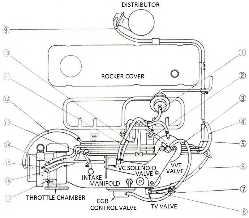
Vacuum Piping Figure
4-3 バキューム配管実態図
4-3 Vacuum Piping Figure
Page 45 Page 47 PDF

長さ length
識別色 identification color
緑 green
白 white
青 blue
黄 yellow
桃 peach
部位 part
No 長さ    識別色   部位
 1 170mm (green)  vacuum gallery - pressure regulator
 2  90mm (peach)  VVT tube - VVT valve
 3 200mm (white)  VVT valve - TV valve side 3-way connector
 4  70mm (yellow) vacuum gallery - distributor side 3-way connector
 5  50mm (yellow) vacuum gallery - distributor side 3-way connector
 6 190mm (white)  vacuum gallery - TV valve
 7 170mm (white)  EGR control valve - TV valve side 3-way connector
 8 110mm (white)  TV valve - 3-way connector
 9 540mm (yellow) distributor - 3-way connector
10 120mm (blue)   vacuum gallery - VC solenoid valve [Vacuum Cut]
11 200mm (blue)   VVT valve - VC solenoid valve
12 200mm (blue)   throttle chamber - vacuum gallery
13  90mm (green)  vacuum connector - vacuum gallery
14 130mm (yellow) throttle chamber - vacuum gallery (distributor use)
15 230mm (blue)   throttle chamber - VC solenoid valve
16 170mm (white)  throttle chamber - vacuum gallery (EGR control valve use)
17 blanking cap
Air Cleaner and EAI
5. エア クリナー及び二次空気導入(EAI)装置 Air Cleaner and Exhaust Air Induction (EAI) Equipment
Page 46 Page 48 PDF

left caption: 接続ホース Connecting Hose
right caption: EAI バルブ Valve
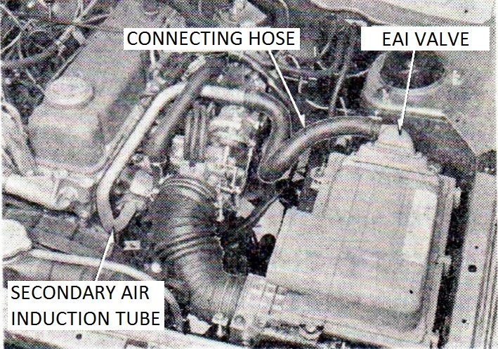 full | Japanese
lower caption: 二次空気導入チューブ Secondary air induction tube
EAI Hose
5.1
EAI Valve
5.2
Page 47 Page 49 PDF

EAI Tube
5.3
Engine Electrical
6. Engine 電装 Electrical
Page 48 Page 51 PDF

Distributor
6.1 Distributor [points type]
Hitachi D4A7-01
Mitsubishi T4T00475
Centrifugal Advance 12 degrees maximum @ 2400 rpm:
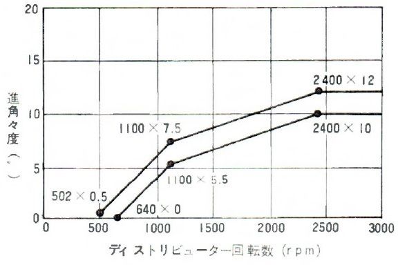 full
full
Vacuum Advance 13.5 degrees maximum:
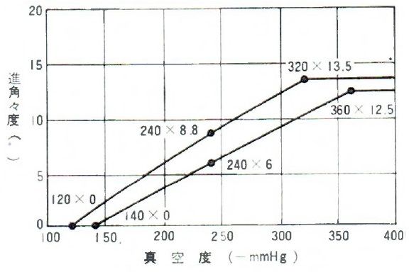 full
full
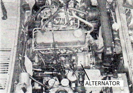
Alternator
6.2 Alternator
IC internally regulated
Hitachi LR150-36
Mitsubishi AQ2250C31
PA10 EGI [Datsun Stanza]
Fuel System
[page 49 original, page 52 PDF] K 7. 燃料系統 Fuel System
燃料系 Fuel System
基本的には、キャブレーター仕様とはぼ同じですが、燃ホースの径がー部異なります。Basically, it is the same to pot and carburetor specifications - diameter of the fuel hose differs.
仕様 Specification
...
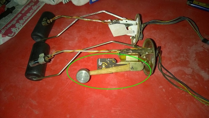
フューエル ゲージ  ユニット Fuel Gauge Unit
サーミスター式(GL以上)
Carburetor: Thermistor type (GL or more)  EGI: Thermistor type
...
フューエル チューブ Fuel Tube
  アウトレット       Outlet  6.35mm carburetor  12mm EGI
  リターン          Return  6.35mm carburetor   8mm EGI
Exhaust System
[page 49 original, page 52 PDF]
8. 排気系統 Exhaust System
排気系 Fuel System
排気系は、触媒コンバータ(サイズ、容量)、... Exhaust system, catalytic converter (size, capacity), ...
Chassis
See PART 2
Chassis
 * Propeller Shaft
Body
See PART 2
 * Accent Stripe
 * Rear Emblem
 * Rear Floor Insulator
Body Electrical
See PART 2
 * Wiring and Relays
 * Tachometer
 * Washer Tank
 * Air Conditioner (Cooler Option)

![[Datsun 1200 encyclopedia]](/wiki/upload/wiki.png)

