![[Datsun 1200 encyclopedia]](/wiki/upload/wiki.png)
| Revision as of 01:24, 20 April 2014 ddgonzal (Talk | contribs) (->510 Switched-Earth Wiring) <- Previous diff |
Revision as of 02:02, 20 April 2014 ddgonzal (Talk | contribs) (->510 Switched-Earth Wiring) Next diff -> |
||
| Line 74: | Line 74: | ||
| == Relay == | == Relay == | ||
| [http://www.showcargarage.com/gallery/files/1/1974DatsunHeadlightRelay03.jpg top]:<img size=140>http://www.showcargarage.com/gallery/files/1/1974DatsunHeadlightRelay03.jpg</img> [http://www.showcargarage.com/gallery/files/1/1974DatsunHeadlightRelay02.jpg side]:<img size=140>http://www.showcargarage.com/gallery/files/1/1974DatsunHeadlightRelay02.jpg</img> [http://www.showcargarage.com/gallery/files/1/1974DatsunHeadlightRelay01.jpg bottom]:<img size=140>http://www.showcargarage.com/gallery/files/1/1974DatsunHeadlightRelay01.jpg</img> | [http://www.showcargarage.com/gallery/files/1/1974DatsunHeadlightRelay03.jpg top]:<img size=140>http://www.showcargarage.com/gallery/files/1/1974DatsunHeadlightRelay03.jpg</img> [http://www.showcargarage.com/gallery/files/1/1974DatsunHeadlightRelay02.jpg side]:<img size=140>http://www.showcargarage.com/gallery/files/1/1974DatsunHeadlightRelay02.jpg</img> [http://www.showcargarage.com/gallery/files/1/1974DatsunHeadlightRelay01.jpg bottom]:<img size=140>http://www.showcargarage.com/gallery/files/1/1974DatsunHeadlightRelay01.jpg</img> | ||
| + | |||
| + | 25230-28000 ASSY RELAY,LIGHT -0874 | ||
| + | 25230-B8000 ASSY RELAY,LIGHT 0974- | ||
| + | B5230-H6185 ASSY RELAY,LIGHT 0876-0777 <> 25230-89965 $48 USD | ||
| + | not applicable 1978-1979 | ||
| + | |||
| + | 25230-89965 | ||
| + | * headlight relay | ||
| + | * floor sensor relay | ||
| + | |||
| + | 25230-H1604 RELAY-INHIBIT -0973 | ||
| + | 25230-B7911 RELAY-INHIBIT 0974- | ||
| = 510 Switched-Earth Wiring = | = 510 Switched-Earth Wiring = | ||
| Line 119: | Line 131: | ||
| Parking Brake pilot lamp is grounded via Handbrake switch | Parking Brake pilot lamp is grounded via Handbrake switch | ||
| G Pin 8 goes to 4-way Flasher Switch | G Pin 8 goes to 4-way Flasher Switch | ||
| + | |||
| + | == Relay == | ||
| + | Late relay | ||
| + | |||
| + | 1969-1972: The two relays on the back side of the RH strut tower in front of the fuse box are for the headlights and the horn. The headlight relay has a 6 prong plug, the horn has four individual wires. | ||
| + | |||
| + | 1973 relay is on the RH side behind the headlights | ||
| + | |||
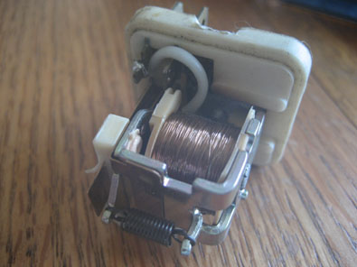
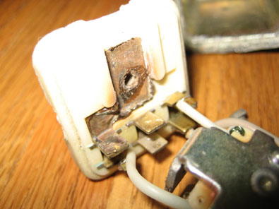
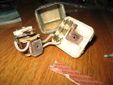
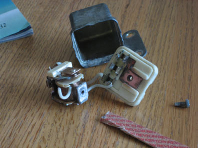
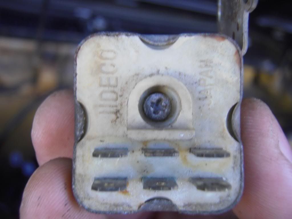
| + | Original JIDECO relay | ||
| + | |||
| + | [http://i20.photobucket.com/albums/b223/vibmx/P4040356_zpsd9c1d13a.jpg http://i20.photobucket.com/albums/b223/vibmx/th_P4040356_zpsd9c1d13a.jpg] [http://i20.photobucket.com/albums/b223/vibmx/P3300343_zpsf8d20b06.jpg http://i20.photobucket.com/albums/b223/vibmx/th_P3300343_zpsf8d20b06.jpg] [http://i20.photobucket.com/albums/b223/vibmx/P3300345_zps78460418.jpg http://i20.photobucket.com/albums/b223/vibmx/th_P3300345_zps78460418.jpg] [http://i20.photobucket.com/albums/b223/vibmx/P3300347_zps2f150968.jpg http://i20.photobucket.com/albums/b223/vibmx/th_P3300347_zps2f150968.jpg] [http://i20.photobucket.com/albums/b223/vibmx/P3300349_zpsa539b5ca.jpg http://i20.photobucket.com/albums/b223/vibmx/th_P3300349_zpsa539b5ca.jpg] | ||
| Low Beam Relay | Low Beam Relay | ||
Revision as of 02:02, 20 April 2014
Early Datsun 620 for North America used used a relay. Later 620 was made more reliable to discarding the relay. 620 does not use switched-earth headlight wiring like the Datsun 510.
Contents |
4-headlight system
High - 4 lamps light up (high filaments)
Low - 2 lamps light up (low filaments)
So the low beams go OFF when the high beams come on. All four headlamps with light, but only on the high circuits.
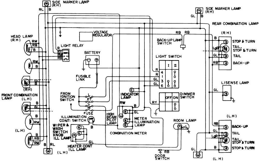
Non-relay Type
Power for the headlamps comes via the Fuse Box, specifically the 'L' (lamp) fuse. The headlight switch provides power OUT when pulled to the 3rd position. From there power goes to the Dimmer Switch on the steering column. Depending on the lever position power is switched to the High Beams or the Low Beams.
LOW  - RB wire (Red wire with Black stripe)
HIGH - RW wire (Red wire with White stripe)
GROUND - headlight sockets are grounded at earth point
         in engine room via engine room wiring harness
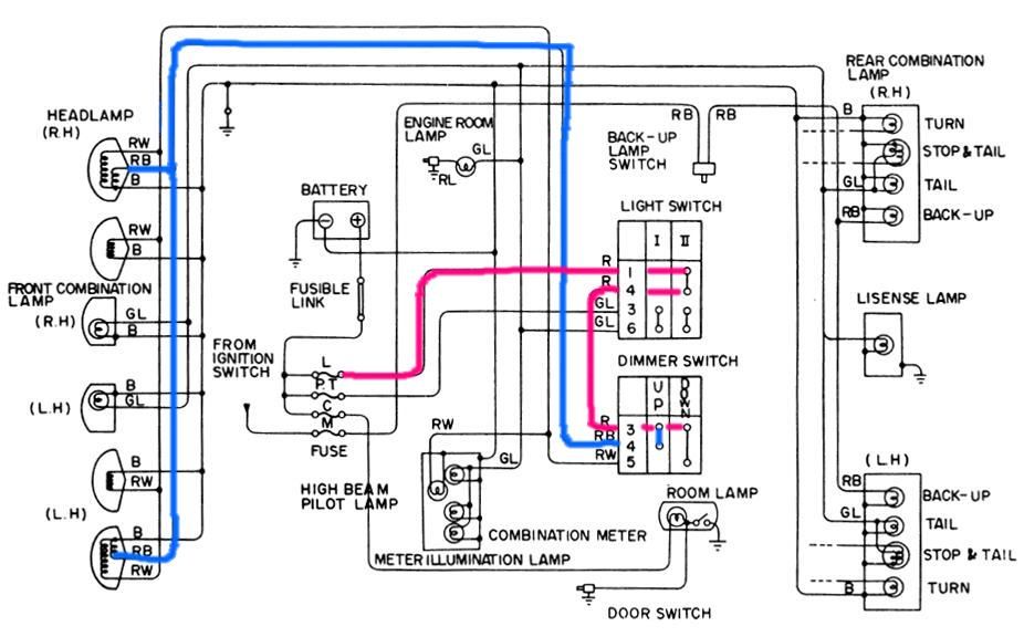
Relay Type
Used in North America 1972-1977. Later 1978-1979 models did not use a relay.
The same Lighting Switch is used. Power OUT is sent to the relay instead of the Dimmer Switch.
The Dimmer Switch differs - it is much simpler. Power is not routed through the Dimmer Switch. When in High Beam position, it grounds the Relay coil to switch the beams. The Relay is located in the engine compartment.
1974 620 North America lighting diagram
Fuses
Power for the headlamps comes via the Fuse Box, specifically the 'L' (lamp) fuse in the Fuse Box.
'L' 15A head Lamp fuse
* High beams
* Low beams
* high beam pilot lamp in dash cluster
The Parking lights are on their own fuse. But still goes through the Lighting Switch. Headlight fuse can be burned out and P light work fine.
'PT' 10 AMP Park lights, Tail lights
* Meter illumination lamps in dash (except T/S and high beam lamps)
* Parking lamps
* Taillights
* License plate lamp
* Engine room lamp (only works with light switch pulled out)
* For North America
  Wiper knob illumination
  Heater control illumination
Stop lights and Hazards on yet another fuse.
'H' 15 AMP Horn, Stop lights, Hazard lights
* Hazard lamps (North America)
* Stop lamps
Reverse lamps on a different fuse.
'M' 10 AMP Meter, Reverse Lights, Alternator Regulator
* Reverse light
* Turn Signal lights
The Room Lamp is independent of headlight circuit. It doesnt go through the Lighting Switch. It has its own fuse.
'C' 15 AMP Radio, Clock, Cigarette lighter, Room lamp
Relay
1978-1979 model year did not use a relay.
1972-1977 used a relay on for North America models.
25230-28000 ASSY RELAY,LIGHT -0874
25230-B8000 ASSY RELAY,LIGHT 0974-0776
25230-89965 ASSY RELAY,LIGHT 0876-0777
Relay


25230-28000 ASSY RELAY,LIGHT -0874
25230-B8000 ASSY RELAY,LIGHT 0974-
B5230-H6185 ASSY RELAY,LIGHT 0876-0777 <> 25230-89965 $48 USD
not applicable 1978-1979
25230-89965
* headlight relay
* floor sensor relay
25230-H1604 RELAY-INHIBIT -0973
25230-B7911 RELAY-INHIBIT 0974-
510 Switched-Earth Wiring
Headlights are not permanently grounded as in newer Datsuns
Headlights are permanently connected to HOT via the Fuse Box
Original 1968-1969 6-fuse fuse box
One fuse powers both Headlights
1969-1973 Dual-Fuse Headlight CircuitNew for 1969 8-fuse modular fuse box 'HL' 10A RL Power to Left Headlights 'HR' 10A R Power to Right Headlights
Relay switches ground on for either
* High beams (all 4 lights)
* Low beams (2 outer lights)
Relay does not switch the 12V HOT side
Relay switches the GROUND wires
Relay Coil is powered by GL wire from Lighting Switch
Relay Coil is switched by BR wire from Dimmer Switch
* ungrounded = Low beams switched to Ground
* grounded = High beams switched to Ground
Dimmer Switch
* Only connects to Ground (High beam position) or disconnected
* No 12V runs through it
Lighting Switch
* controls headlights, park lights, dash illumination lights
* does not control turn signals
* does not control dash pilot lights (OIL, CHG, P.B)
Dash Illumination Lamps (2) are grounded though Pin 2 Black wire.
GW Pin 1 goes to Lighting Switch
OIL pilot lamp is grounded via Oil Pressure switch
G Pin 8 goes to 4-way Flasher Switch
CHG pilot lamp is grounded via Voltage Regulator
G Pin 8 goes to 4-way Flasher Switch
Parking Brake pilot lamp is grounded via Handbrake switch
G Pin 8 goes to 4-way Flasher Switch
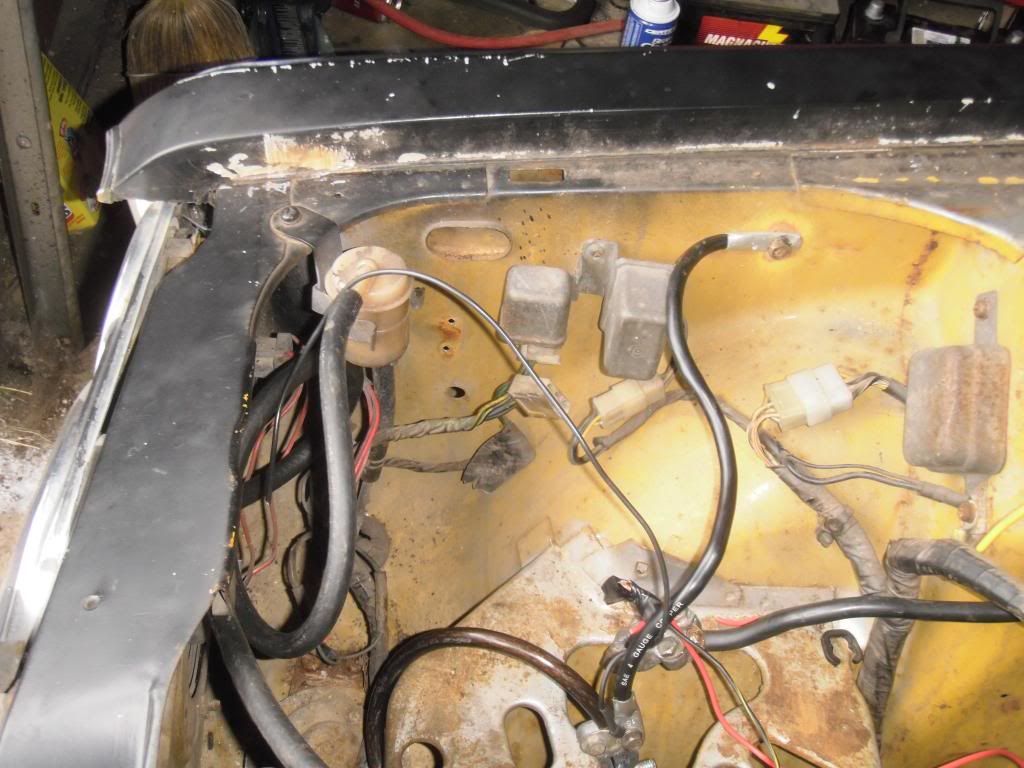
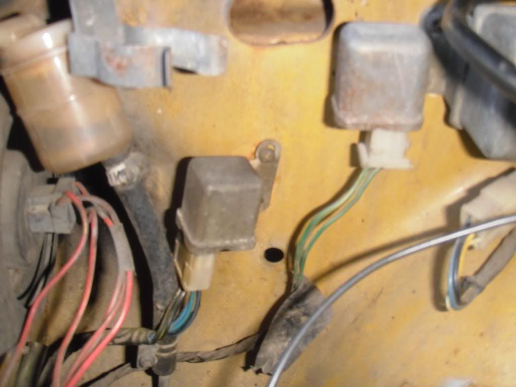
Relay
Late relay
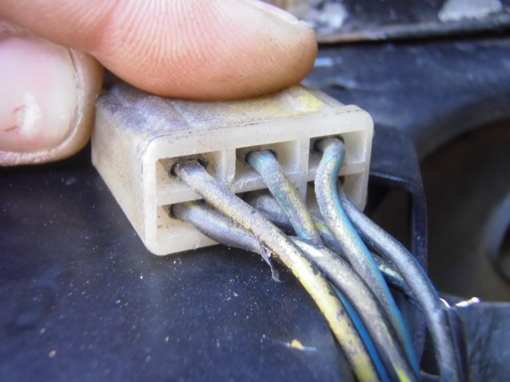
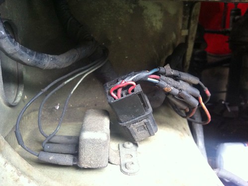
1969-1972: The two relays on the back side of the RH strut tower in front of the fuse box are for the headlights and the horn. The headlight relay has a 6 prong plug, the horn has four individual wires.
1973 relay is on the RH side behind the headlights
Original JIDECO relay
Low Beam Relay
B5230-28000
3-wire horn relay
Headlight Relay
Headlight Relay
B5230-89985
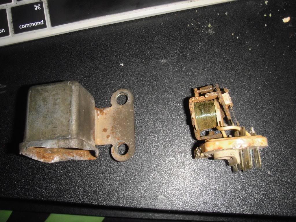
Relay Repair
http://www.510coop.com/completed/HLrelay.htmCarefully pry the cover loose. there are four crimps, one on each side. uncrimp carefully with a screwdriver and remove the cover. Now between the contact on the bottom of the plastic piece is a screw. Remove it and carefully lift the guts away from the base and you should see rust on the bottom. Sand that clean apply so dielectric grease, reassemble and you should have a working relay. It's the rust and corrosion that is interrupting the circuit. Be careful of the wiring in the relay. The unit itself is pretty tough but some of those fine wires can break if you get too rough.
So, that's what I did...and now I have headlights! Thanks Bruce!