![[Datsun 1200 encyclopedia]](/wiki/upload/wiki.png)
The Differential must be adjusted to specifications when changing the bearings, the Ring & Pinion (Crown Wheel & Pinion) or when rebuilding it. Yet, in USA and Australia it is faster and less expensive — and more reliable — to replace with a good used differential than it is to rebuild one. Many rebuilds have not turned out well. However, if you are good with detail, have the proper measuring tools, or use an expert mechanic a rebuild can be done.
Contents |
Overview
Outline of Side Bearings & Ring & Pinion replacement
- Measure the bearing preload. Then get the variation numbers off the gear case. These are A, B, C, D and H' in the figures below. The numbers are used to calculate the shim selections
- After assembly and final torque, the gear backlash is measured with a micrometer, and if necessary, shims are moved from side to side to bring the backlash into specification
- Then runout is checked. Throw away the Ring & Pinion if out of spec
- Then bearing preload torque is measured, and if necessary, the shims altered
- Finally, the tooth pattern contact is checked. If adjustments are needed, the backlash may need to be adjusted again
Pinion Oil Seal Replacement
38189-18000ᴳ Pinion seal
* TB 32x58x12ᴳ
* SKF 550219ᴳ
1. Place car on jacks or hoist
2. Remove drive shaft & drive flange
3. replace seal
4. Tighten nut to 12-17 kg-m (87-122 ft-lb)
5. reverse steps 2 & 1
Do you need a new crush sleeve? Although Datsun insisted a new crush sleeve be used, using a 0.25 mm shim seems to work. On the other hand, if you do not change the bearing and do not move the crush sleeve, just replacing the seal and torquing to spec worked for me. You'll know if your diff stays quiet. See POST Pinion oil seal
Pinion Bearing Crush Sleeve
B110 H145 used a crush sleeve. Older H145 doesn't use one, instead they used a fixed length sleeve on the pinion with shims to control the bearing preload. The shape of the pinion shaft between the bearings is different between the two versions of the diff so the earlier sleeve can't be used on the later pinion.
NOTE: "pinion bearing adjust spacer" (crush sleeve) is NLA, yet needed for a proper rebuild — even for just changing the gears.
You can reuse the crush sleeve by adding a thin shim (0.25mm / 0.010 inch) between the tube and the bearing. It's just enough so that the sleeve can be re-crushed to archive preload. See POST H145 Bits Needed
38165-H1001  Pinion gear bearing spacer (#crush sleeve)
38216-H1000  Pinion yoke nut (reuse if possible)
Bearing Preload is critical:
- too tight (bearing will eventually seize with a bang)
- too loose (seal failure with oil leak, whine noise, and crown wheel to pinion depth will change)
Preload

Another reuse account: POST Who cares?
- Measure length of tube, record
- Place tube over steel bar and lightly hit the bulge all the way around evenly
- Remeasure, 0.5 to 1mm longer would be good
- Reinstall crush tube and set pinion seal/bearing preload
Side Bearing Shims
The Ring and the Pinion are both marked with variation numbers. These are A, B, C, D and H' in the figures below.
A. The numbers marked on the diff carrier are used to calculate the shim selections and the parts assembled
B. Gear backlash is measured with a micrometer, and if necessary, shims are moved from side to side to bring the backlash into specification
C. Runout is checked
D. Bearing preload torque is measured, and if necessary, the shims altered
E. Finally, the tooth pattern contact is checked. If adjustments are needed, the backlash may need to be re-adjusted
Setting and adjusting side bearing shims

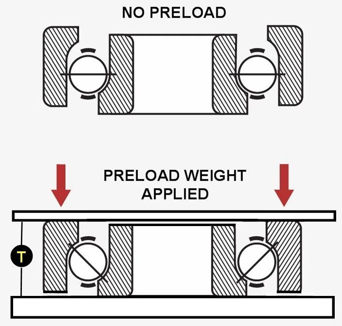
1. Place an approximately 2.5 kg (5.5 lb) weight on the side bearing, and measure bearing thickness
Standard side bearing width: 17.5 mm (0.689 in)
Note: With the weight placed on the side bearing, turn the bearing two to three turns, and measure thickness.
Use an inside micrometer to measure 'T'
[Calculate E and F
   E = Left  Measured Thickness - 17.5 mm
   F = Right Measured Thickness - 17.5 mm
   Example: 17.52 mm - 17.5 mm =  0.02 mm
            17.49 mm - 17.5 mm = -0.01 mm]
2. Side bearing adjusting shim thickness calculating formula
  Left side (drive gear side)
    T1=(A-C+D-H')× 0.01 +0.2 + E (mm)
  Right side (pinion mate side)
    T2=(B-D+H)×0.01+0.2+F (mm)
Figures for A, B, C, D and H' are dimensional
variations in a unit of 1/100 mm against each
standard measurement.
   Where
   A = The figure marked on the left side bearing housing
       of gear carrier.
   B = The figure marked on the right side bearing housing
       of gear carrier.
   C&D = The figure marked on the differential case.
   E&F = These are differences in width of left or right
         side bearing against the standard width 17.5 mm
         (0.6890 in). Figure is given in a unit of 1/100 mm.
  Fig. PD-26 Thickness of shim on left side
     Thickness of shim on right side
H' = The figure marked on the ring gear.
Example of calculation
  A=1 B= 2 C=-2 D=3
  E=+0.02 mm F=-0.01 mm H'=+1
Left side
T1=(1-2+3-1)×0.01+0.2+0.02= 0.23 mm
Right side
T2=(2-3+1)×0.01+0.2-0.01=0.19 mm
Apply a 0.23 mm shim and 0.19 mm shim respectively to the left and right, and fit the side bearing using Differential Side Bearing Drift ST33220000.
  Side bearing adjusting shims
  Thickness mm (in)
  0.05 (0.0020)
  0.07 (0.0028)
  0.10 (0.0039)
  0.20 (0.0079)
  0.50 (0.0197)
To automate this formula and lessen mistakes on the shop floor, Datsun provided this slide chart (although you can certainly make the calculations by hand):

3. Install the differential case assembly, together with the side bearing outer race, on the final drive housing.
Note: Be careful not to confuse the right and left sides of the side bearing housing.
4. Install the bearing cap, and tighten the installation bolt to the rated tightening torque.
  Bearing cap tightening torque:
  5 to 6 kg-m (36.2 to 43.4 ft-lb)
Note: Be sure to align match mark put before disassembly correctly.
5. Measure "L" dimension (between left and right bearing cap edges) by a micrometer.
"L" dimension: 153.40 to 153.55 mm (6.0394 to 6.0453 in)
The L dimension is set at the factory by precision machining the pads on the caps.

If the L dimension is incorrect, ensure that there is no foreign matter between the cap and the carrier, and that the left and right bearing caps are not mixed up.
6. Upon completion of reassembly, measure drive pinion/ring gear backlash. When backlash is less than the rated value, move the side bearing adjusting shim from the left side (ring gear side) to the right side. When backlash is more than the rated value, move the side bearing from the right to left contrarily.
Backlash: 0.10 to 0.15 mm (0.0039 to 0.0059 in)
Fig. PD-28 Measuring backlash
7. Existence of foreign matter between the drive gear and differential case is considered when backlash fluctuates considerably. Measure drive gear back deflection.
8. Check the run-out of ring gear side is within 0.05 mm (0.0020 in) total indicator reading.
Fig. PD-29 Measuring run-out of ring gear
9. When run-out of ring gear is normal and fluctuation of backlash is considerable, replace the gear set. Before replacing the gear set, be sure to measure companion flange deflection. Fluctuation of backlash may be considerable due to deflection of pinion bearing.
  Limit of deflection:
  A portion:
    Less than 0.05 mm (0.0020 in)
  B portion:
    Less than 0.05 mm (0.0020 in)
Fig. PD-30 Measuring place
10. At the same time, check bearing preload. Bearing preload should read 8 to 15 kg-cm (6.95 to 13.03 in-lb) of rotating torque [2.3 to 4.3 kg (5.1 to 9.5 lb) at companion flange bolt hole].
If preload does not accord with this specification, adjust it with side bearing shims.
11. Check and adjust the tooth contact pattern of ring gear and drive pinion.
  (1) Thoroughly clean ring and drive pinion gear teeth.
  (2) Paint ring gear teeth lightly and evenly with a
       mixture of powdered red lead and oil of a suitable
       consistency to produce a contact pattern.
  (3) Rotate pinion through several revolutions in the
      forward and reverse direction until a definite contact
      pattern is developed on ring gear.
  (4) When contact pattern is incorrect, readjust thickness
      of adjust shim.
Be sure to wipe out red lead completely upon completion of adjustment.
(5) Incorrect contact pattern of teeth can be adjusted in the following manner.
   a. Heel contact
      To correct, increase thickness of drive pinion adjusting
      washer in order to bring drive pinion close to ring gear.
Fig. PD-3 Heel contact
   b. Toe contact
      To correct, reduce thickness of drive pinion adjusting
      washer in order to make drive pinion go away from ring
      gear.
Fig. PD-32 Toe contact
   c. Flank contact
      Adjust in manner similar to b.
Fig. PD-33 Flank contact
   d. Face contact
      Adjust in manner similar to a.
Fig. PD-34 Face contact
e. Correct tooth contact
Fig. PD-35 Correct contact
Note: Change in thickness of adjusting washer is accompanied by change in backlash. Check it when installing gear.
Common Problems
Whining
I would not worry about a slight humming from the differential. Many of them do that. As long as you keep the oil level full, it should get no worse.
However, severe humming (whining) caused by a loss of oil will not go away. After you add oil, the diff will work OK but will never be quiet again. It can last for years making a bit noise. It may help to reset the gearset to the proper clearance, which won't stop the whine but will bring the backlash back into tolerance.
Whining could be a wheel bearing:
- wheel bearing: the whining get louder when turning one direction, and goes away in the other direction
- diff bearing: whining changes with the load. When slightly accelerating, it whines. When coasting the whine lessens
Knocking/Grinding
Knocking is caused by a worn part (probably a bearing) which must be replaced. It could be a side bearing or the pinion bearing.
It could also be caused by a chipped gear tooth.
To isolate this from a bad transmission bearing, drive at varying speeds. Put the gear lever in neutral temporarily. Does the knock occur in neutral? Then it is likely to be in the differential.