|
|
Browsing this Thread:
1 Anonymous Users
|
|
Re: racetech's 1200 SR20VE Project |
|
Home away from home  
Joined:
2009/4/16 10:37
From Cape Town, South Africa
Group:
Registered Users
|
Posted on: 2010/7/28 9:55
Edited by racetech on 2010/7/30 8:46:21
Edited by racetech on 2013/12/24 6:40:40
|
|
|
|
|
Re: racetech's 1200 SR20VE Project |
|
Home away from home Joined:
2009/4/16 10:37
From Cape Town, South Africa
Group:
Registered Users
|
29 May 2010 Transmission Tunnel Finished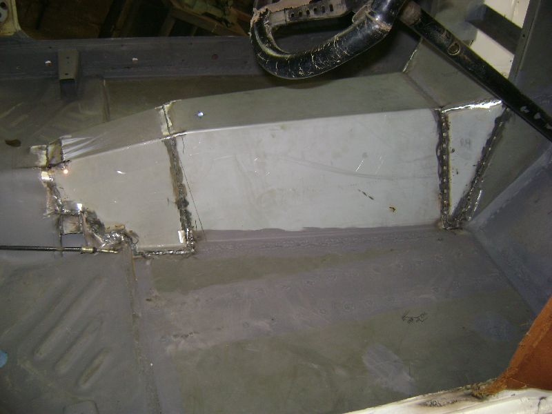 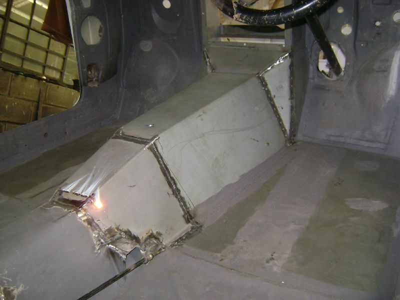 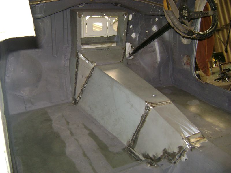 Work started with bending and shaping the two front covers that is located in front of the main piece of the transmission tunnel. They were welded in place and then the bending and shaping of the rear section that mates between the main transmission tunnel and the old one started. This particular one took quite a while to get satisfactory results, as we were working with old and new metal and had to get them nicely blended in to each other. 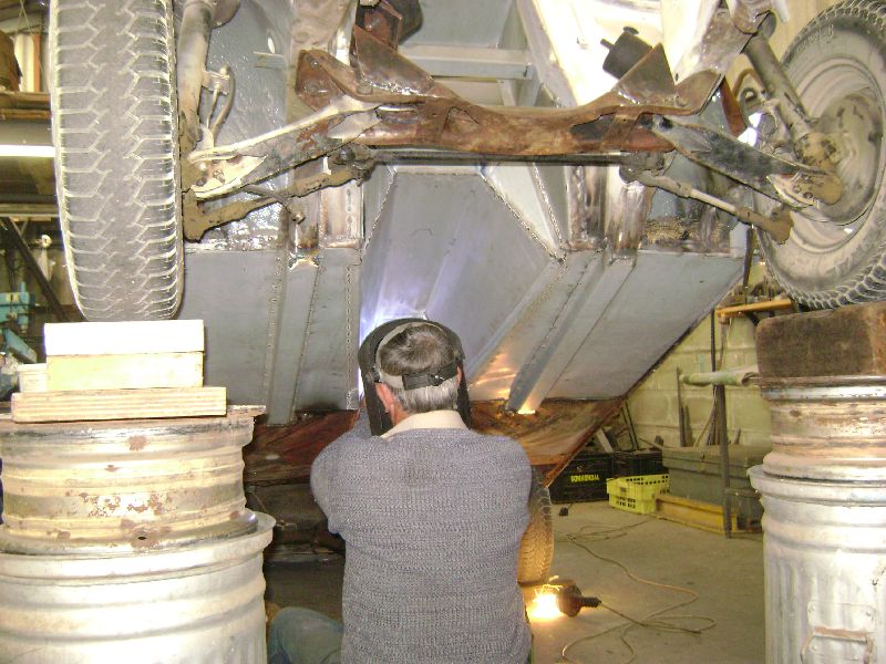 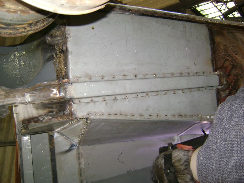 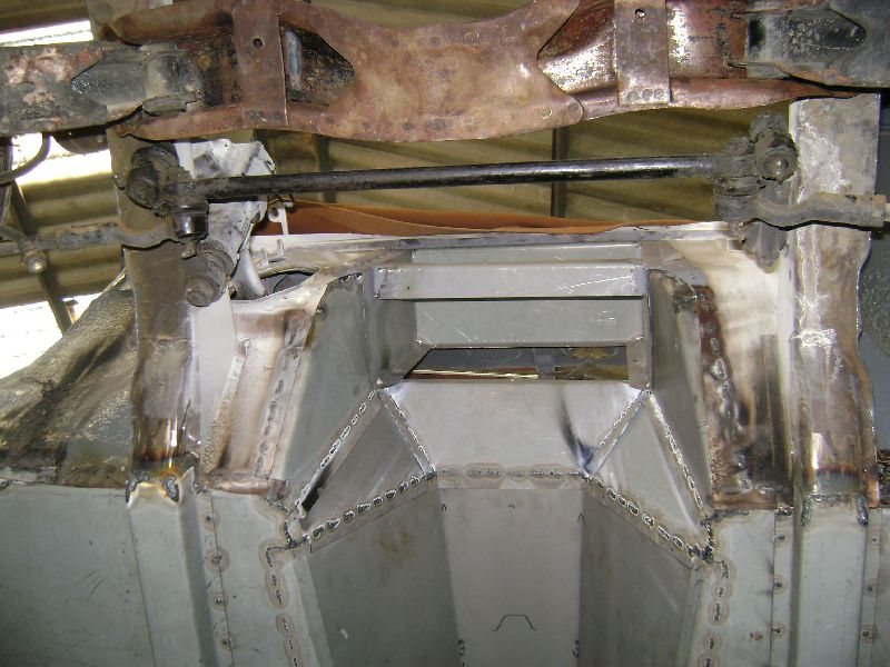 Once all the TIG welding was done on the inside, the old man moved to the underside of the car to do all the welding there, this was a heck of a big job and kept him busy for the rest of the day. As he had to weld the channels to floors, floors to transmission tunnel and all the other pièces in the puzzle. You can actually see him busy welding on the underside while I was taking the photos of the inside, it appears as a bright orange light as the metal heats up. While he was busy I cleaned all the inner welds with the grinder fitted either with a cutting disc or flapper wheel. I must say the flapper wheel gives a real nice finish. All the new metal parts is now double seam welded on the inside and outside of the car. 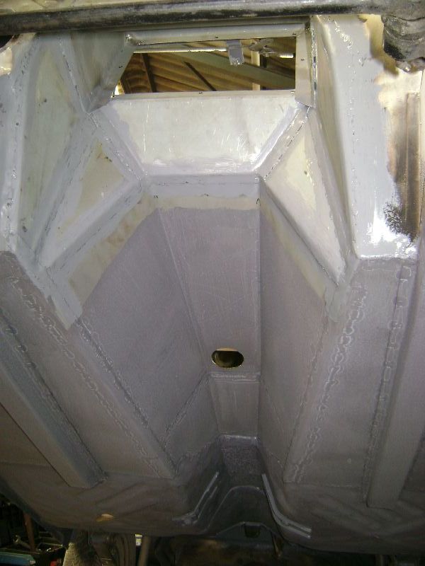 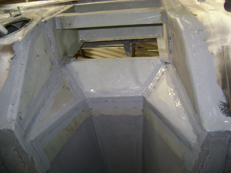  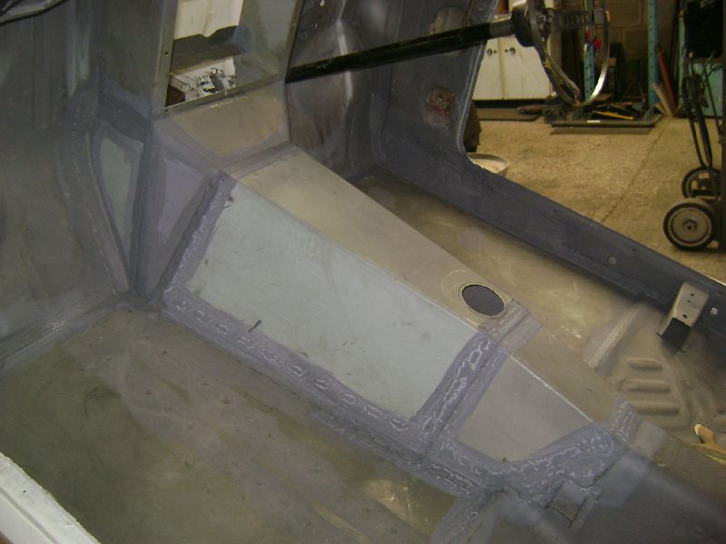 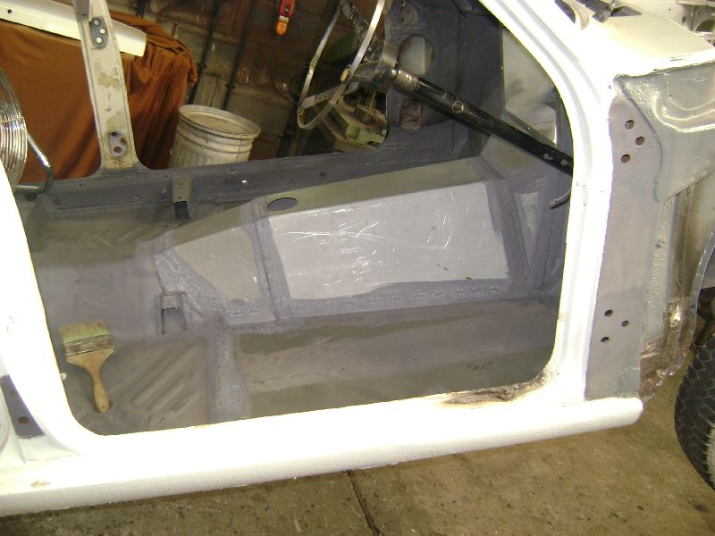 The following day I spend to apply paint to all the seams, new metal and old metal that will stay on the car. All of this was done in preparation to seal all the seams with polyurethane based sealer. In this process another bad patch of rust was discovered just in front of the left rear wheel. Another item added to the list to be fixed.  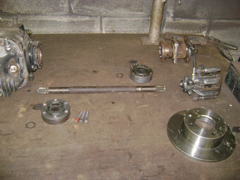 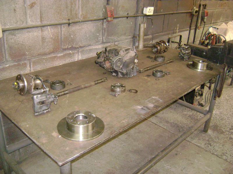 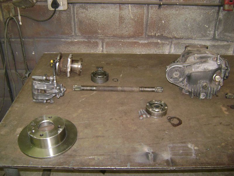 I had a hour or two of time on my hands after the painting and decided to do the machining on the hubs to fit the rotors sourced from a Ford Bantam Bakkie, afterwards I packed all the components of the rear suspension out on the table to start with the planning of the rear suspension. The components on the list is BMW E30 3.64:1 Limited Slip Differential, Ford 3.0Lt Sapphire Hubs, Hub Carriers, CV's and Drive Shafts, braking on the rear will be handled by a set of Volkswagen Golf III GTI calipers on the set of Bantam solid rotors.
Posted on: 2010/7/29 8:58
Edited by racetech on 2013/12/24 6:39:39
|
|
|
|
|
Re: racetech's 1200 SR20VE Project |
|
Home away from home Joined:
2009/4/16 10:37
From Cape Town, South Africa
Group:
Registered Users
|
19 Junie 2010 - Gearbox Mounted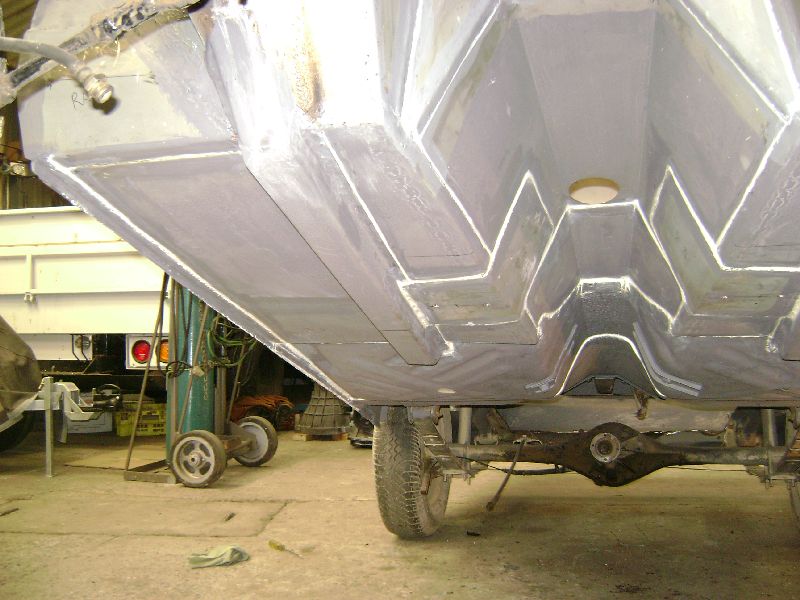  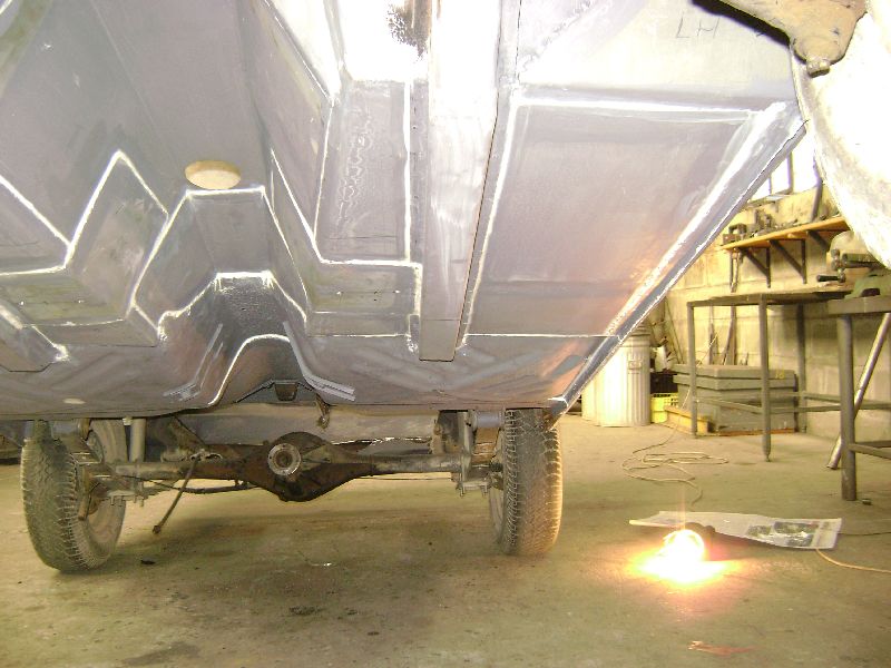 First order of business, get this new floors and transmission tunnel much stronger than the originals as the new gearbox is quite a bit heavier than the old one and I was not going to take changes with the construction and at the end of the day sit with bend floors etc. First of all 2 support plates was welded in on the underside were the gearbox was going to be mounted, they stretch from the support channels to the inside of the gearbox tunnel, this way the gearbox's weight will be carried over a very big area. All the seams was painted and sealed with polyurethane sealer. 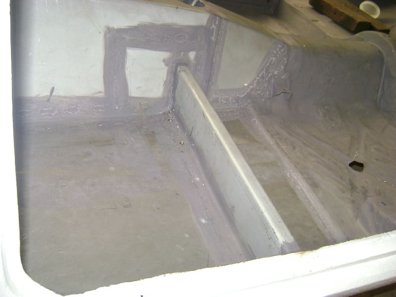 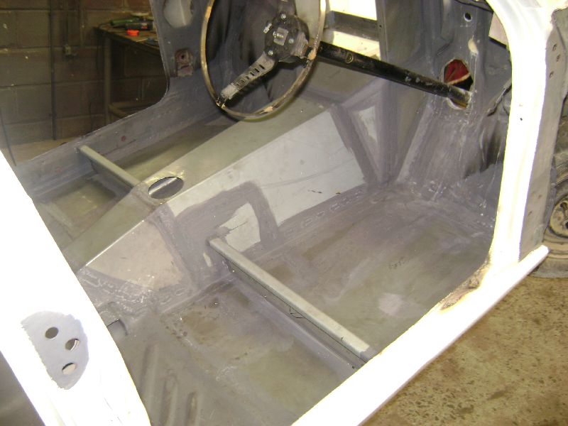 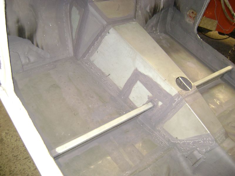 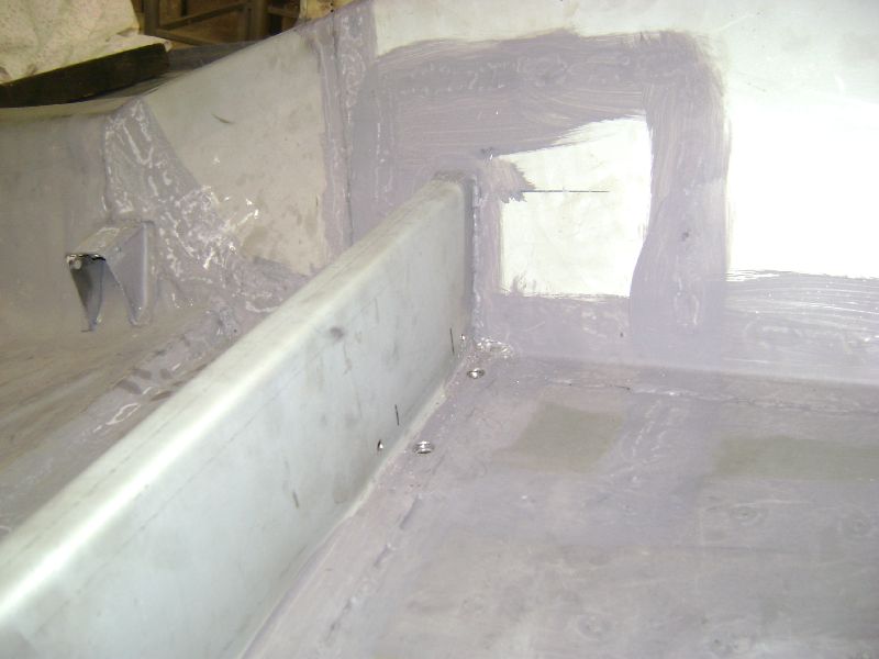 We then moved onto the inside of the car and started fitment of the new seat supports, this took awhile to get all the angles correct as there is a lot of bends in these supports, once we were happy with the fitment the welding started. I must admit, when it comes to working with mild steel sheet metal, there is no better option in my opinion that Electro Galv. This stuff is clean, does not mess oil on your hands, the Tig welder loves it and the added bonus is that it has a electro galvanized coat on as the name suggest; downside, much more expensive than normal hot or cold rolled plate, but worth every cent. 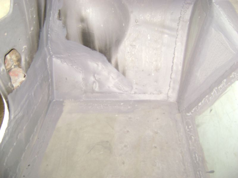 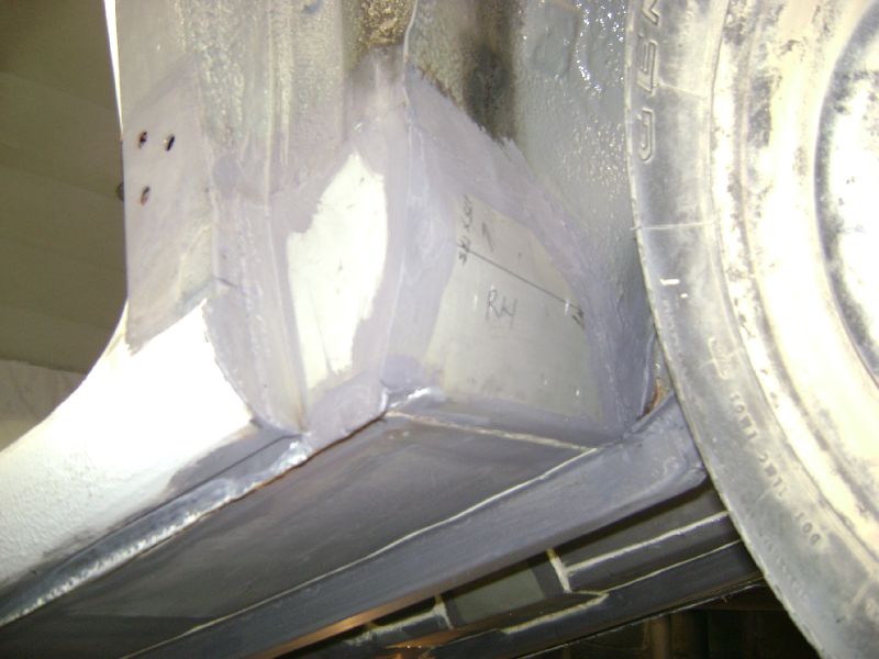 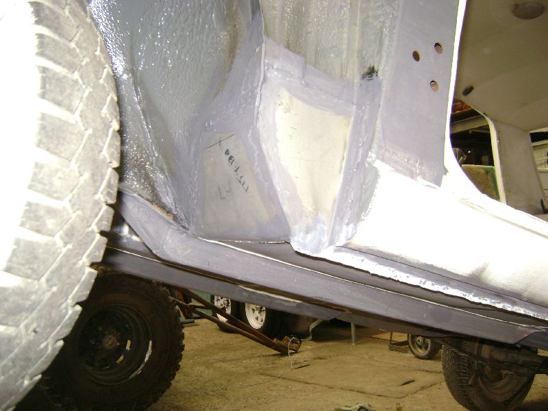 My father started to repair a rust spot on the left hand side of the interior, this one kept us thinking for a while, the metal was so bend and dented, the only way was to remove the whole thing or just cut out the affected piece and cover it again with a plate. I was busy finished the grinding of the welds on the underside. The left and right front wheel arches was also on the list to be done, as we had to get the corners correct after the new floors were joined to the sills and wheel arches.  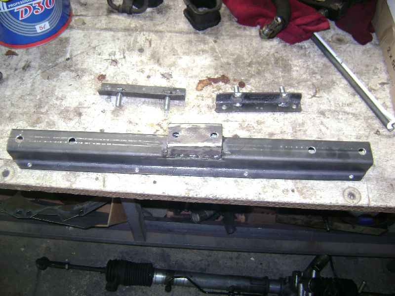 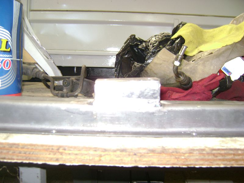 Finally we started with the work set aside for the weekend, the mounting of the gearbox. Our biggest challenge was the positioning of the mounting on the gearbox, obviously we wanted it directly underneath the seat supports for added strength, but if using the original mounting location on the gearbox we would have ended to far forward. After a inspection of the gearbox we decided to move the rubber mounting to the back of the box. This particular mounting spot seems that it is strong enough and could be used for mounting the box in a different application. The gearbox mounting itself was bend and drilled and a piece of metal welded on to the correct angle at which the gearbox sits in the car. To make life easier, we made to little plates containing the bolts that holds the mounting in place, which mounts on the inside of the car and gets bolted to the seat support, no need for another person to hold a spanner to remove the mount. 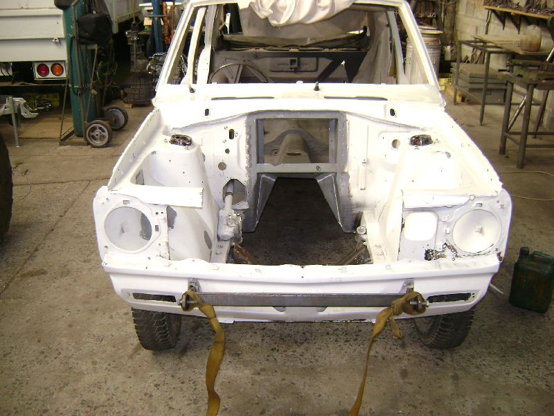 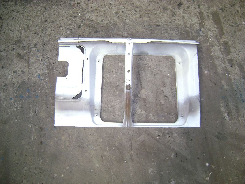 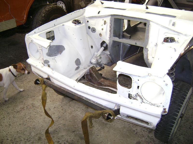 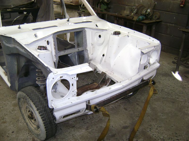 Just before we had to reinstall the motor and gearbox, my father asked me, "what do you think about the idea of making the radiator support a removable unit, as this would aid the removal and installation of the motor and gearbox as a unit much easier", it didn't take me more than 5 minutes to sum up the situation whip out a pencil to draw a few lines and install the thinnest cutting disc in the grinder. Allot of this material that we wanted to cut out was already on the list to remove as we need to make space for the biggest possible radiator to fit the front. Once the radiator arrives we will mount it and start rebuilding the front section which houses the bonnet catch and support, but in such away as it needs to be removable. By removing this piece of material, a nice location for a oil cooler also presented itself. 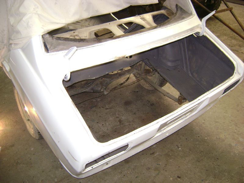 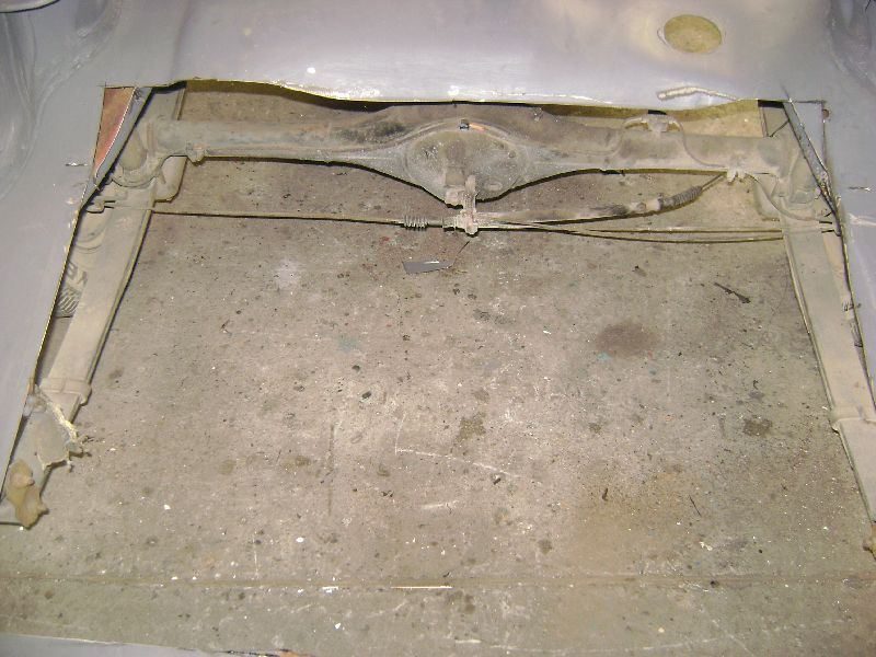 Since we were in the cutting up a Datsun spirit we moved to the rear of the car, in the boot we had to make space for the fuel cell, pumps and filters, the spare wheel hole seemed to be the obvious place to mount these goodies, but the small whole was not going to be enough. We traced the chassis from under the car and cut the biggest whole possible, the idea is to replace the hole with a box to house the above mentioned, an idea that I got from a picture showing a Datsun with a dropped fuel tank. My first thoughts after we cut the hole was that it is going to be a lot easier to design the rear suspension, provided now, that you can actually sit upright in the hole and do the work than lying on your side. 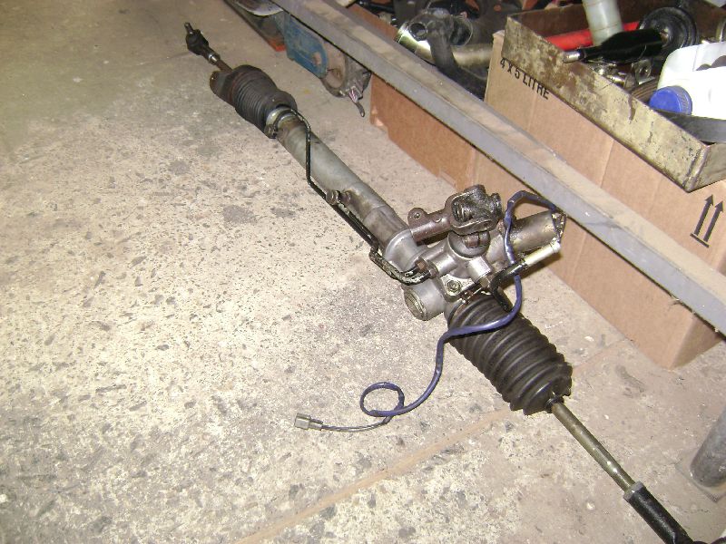 During the previous weeks, i had a little time on my hands and was able to visit some of the local wreckers to source a suitable power steering rack for the car. I only had to options, Nissan Skyline, the last one to be released in South Africa and the Toyota Cressida. These units mount on the rear of the cross member which will help allot with the actual mounting in this application and the other benefit is that if you turn the steering wheel left the wheel would actually move left. The exact opposite applies to units like those in the BMW's that mount on the front of the cross member. I was unable to source a decent Skyline one and had to settle for the Cressida unit. After holding it under the car it seems that the biggest modification that will need to be done to the unit is to machine down the rack ends and cut new thread for tie rods to work on the car. 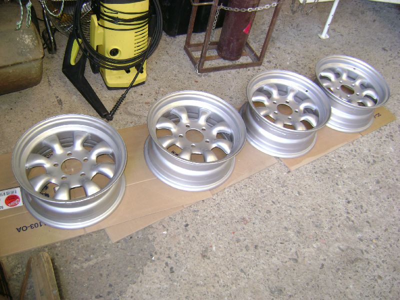 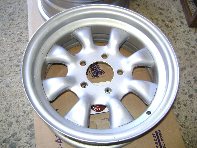  While I was busy on the upper level of the workshop, looking for parts in the containers, my eyes caught a glimpse of a set of Old Cyclone rims. I asked my father if he would donate it to the project and eagerly agreed as both of us knew this is the correct wheel for the car. After taking them down to get cleaned, I realized it is a set of 14" wheels with 5/108 pcd, the answer was easy, weld the holes up, redrill to 4/100 pcd, the pcd I will be converting the whole car to, as more options is available and then use them on the street or for a set of Semi Slicks. Damn these are sexy wheels, now to source 1 or 2 sets of them in 13" for use with low profile slicks.
Posted on: 2010/7/30 8:45
Edited by racetech on 2013/12/24 6:30:11
|
|
|
|
|
Re: racetech's 1200 SR20VE Project |
|
No life (a.k.a. DattoMaster)  
Joined:
2004/10/28 11:35
From Geelong, Vic
Group:
Registered Users
|
dont know if you said it in the post, didnt read the whole thing, but why arent you using the gearbox mount in the stock position on the SR gearbox? im sure it would do a better job of supporing the box in the stock position as its a stronger point in the gearbox and there is less leverage on it as its not at the very back of the box
Posted on: 2010/7/30 9:33
|
|
|
|
|
Re: racetech's 1200 SR20VE Project |
|
Home away from home Joined:
2009/4/16 10:37
From Cape Town, South Africa
Group:
Registered Users
|
It would have messed around with the seat supports that we welded in. Would have been to far to the front then, as I'm going to move the seat backwards. I also wanted the gearbox mounting to be directly beneath the seat supports.
The position were we moved it to know looks like it could be a mounting point in some other application.
Posted on: 2010/7/30 9:38
|
|
|
|
|
Re: racetech's 1200 SR20VE Project |
|
Home away from home Joined:
2009/4/16 10:37
From Cape Town, South Africa
Group:
Registered Users
|
24 July 2010 Rear Suspension Planning - Phase 1  Never in my life will I again under estimate the amount of planning that goes into building your own rear suspension. First you need to decide which configuration will suite your application, I went for the SLA (Short Long Arm) Independent Rear Suspension option, this configuration will provide you with some form of negative dynamic camber as the wheel travel upwards. Next in line is the differential to be used, well this was a easy one, BMW E30 3.64:1 Limited Slip Differential as I had one lying at home gathering dust. Now you have a differential, next in line was the Hubs, CV's, Hub Carriers and Drive shafts, I'm not the biggest fan of Ford, but must admit that the old 3.0 Sapphire solved this piece of mystery. Mounting these parts needed some thinking, luckily this weekend I was able to design the Upright in such a way that a 13" wheel could be used, this upright will be the mounting plate for the Hub Carriers, Upper and Lower Wishbones and the calipers which was sourced from a Volkswagen GTI III rear suspension. Rotors come in the form of Ford Bantam bakkie's front solids. The wishbones was a beast in their own, I decided to use bushes instead of ball joints, sourcing bushes was much easier than figuring out which bush to use. Fisrt of all you need to know exactly what sizes pype you will be using on the outside and inside of the bush. I settled for 34.2 OD X 25 NB X 2.84 SABS 62 MED WT pype for the outside of the bushes, this Pyp has an OD of 34.2mm and ID of 28.52mm Wall of 2.84mm and for the inside of the bush a Seamless cold drawn hydraulic steel tube with OD of 16mm and ID of 12mm. With this selection of pypes I was enabled to source a Polyurethane bush that has a OD of 28mm and ID of 16mm Length of 25mm and I will be able to use a 12mm bolt to secure the wishbone. The body of the wishbone will be made from ASTM A106 GRB SCH40 OD of 33.4mm ID of 26.64mm Wall of 3.38mm, this selection of material will be a good combination between strength and weight if working on a budget, chrome molly would have been great, but at a price only the top teams can afford. 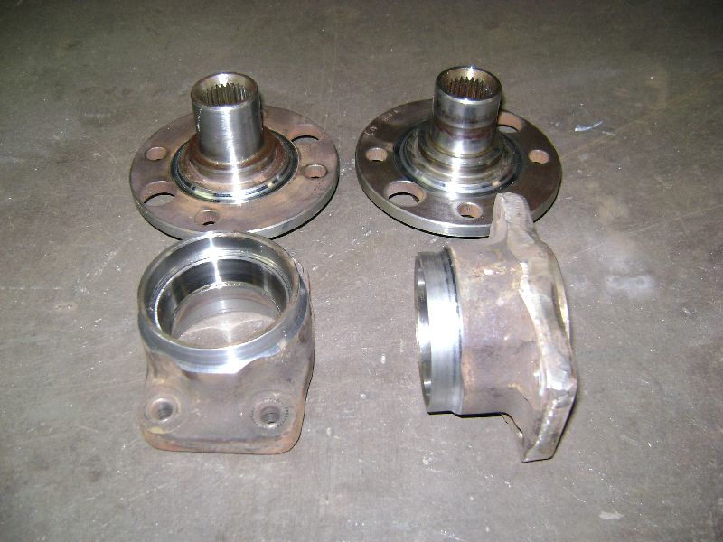 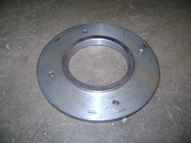 Hub carriers and Hubs was machined to allow the use of Allen Cap Bolts instead of the conventional press in studs. I will tap thread in the hubs and tighten the Allen Caps with Locktite and than spot weld it to keep it in place. A 4/100 pcd template was machined to drill the holes in the hubs which currently is 4/108pcd. 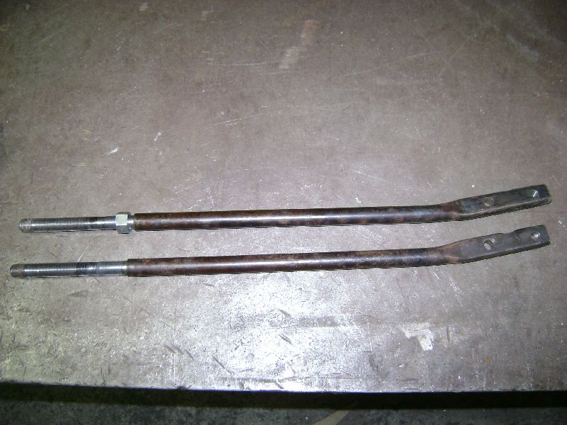 The front track rods was also modified to be adjustable, this would enable me to adjust the front castor in conjunction with camber / castor plates to a exact number that will suite the application or conditions.   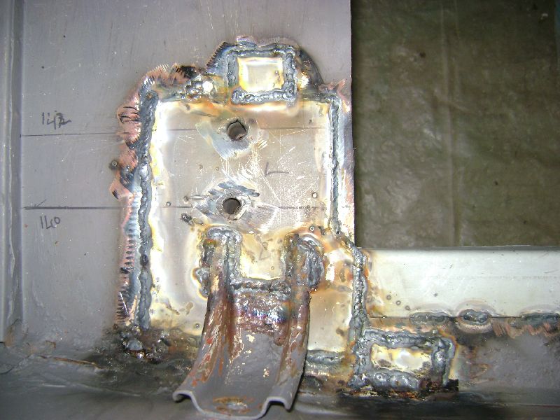 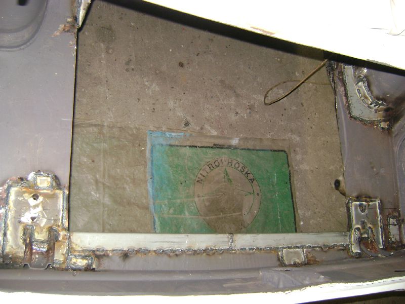 Some rust was removed in the boot and the rear tow bar mounting was reinforced for use as a possible mounting for the rear suspensions sub frame.  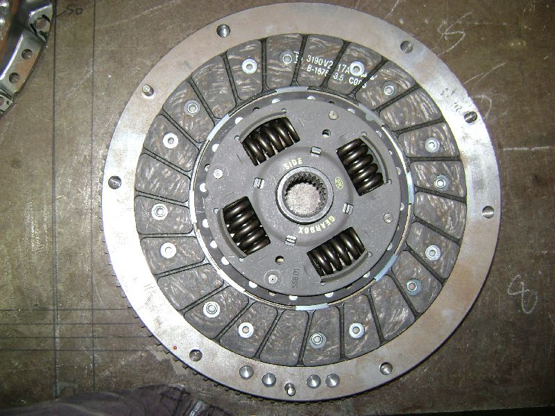 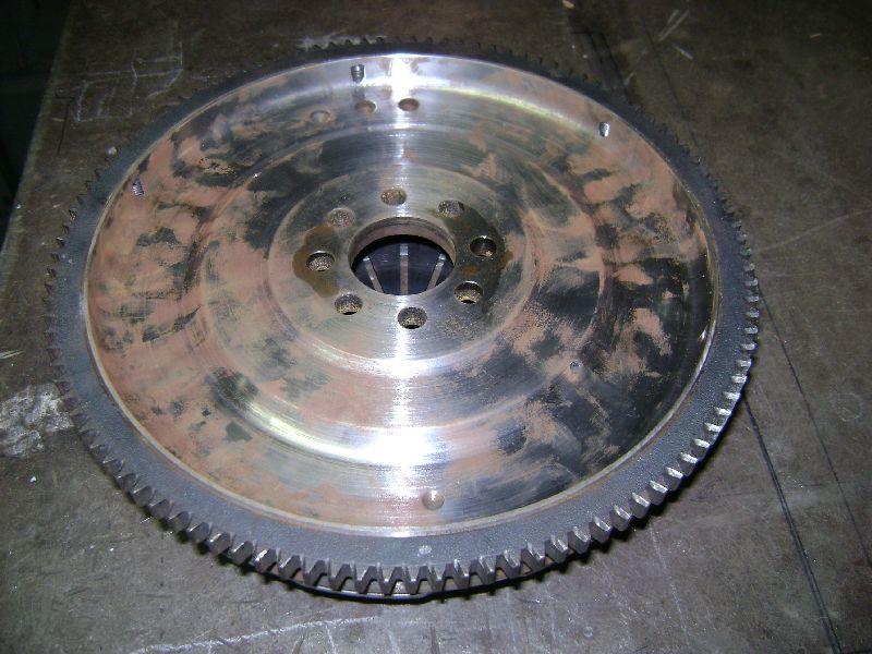  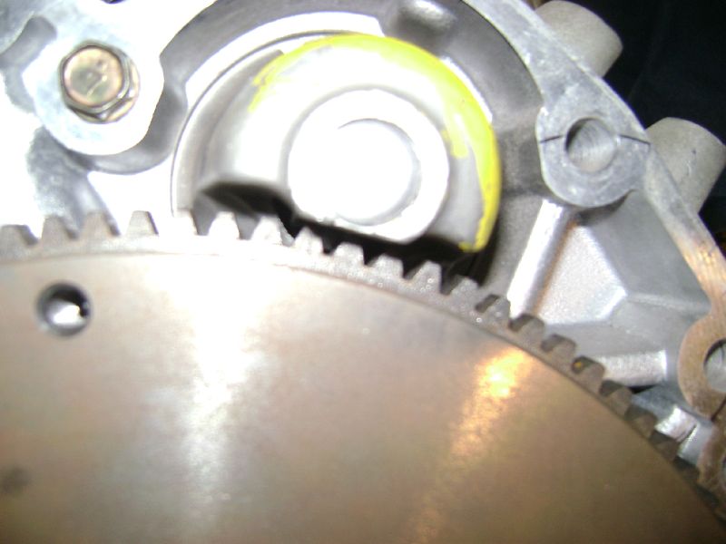 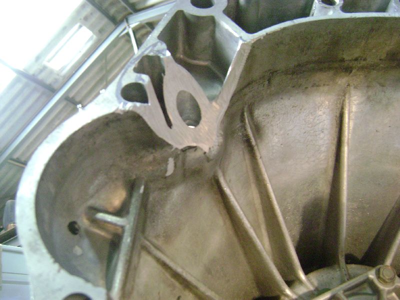 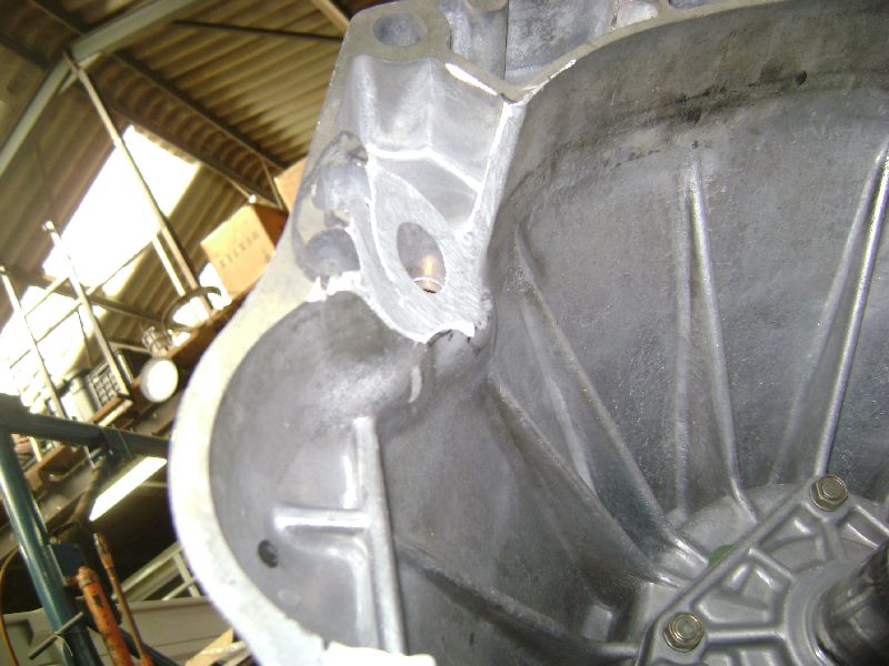 Flywheel and Pressure Plate came back from the machine shop that did a very good job on removing the material behind the ring gear which was the obstacle for the FWD starter and the balancing of these 2 units. We quickly bolted it to the motor to see if the starter will fit, and yes it does. Even when placing power on the solenoid, it kicks in and release. We then bolted the gearbox to the motor and mark the material that needs to be removed in order to use the RWD gearbox with the FWD starter. After a few fitments we had enough removed for the starter to clear the bell housing and not to make a hole thru the bell housing. 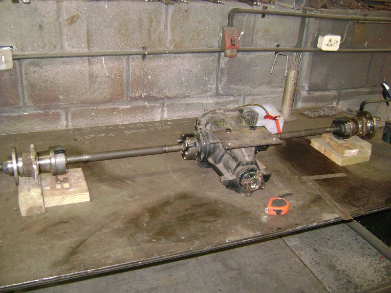  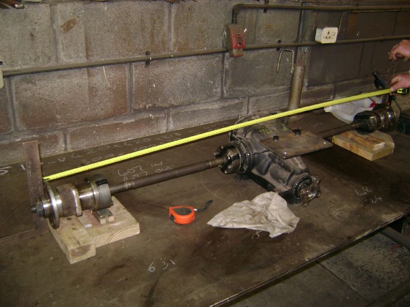 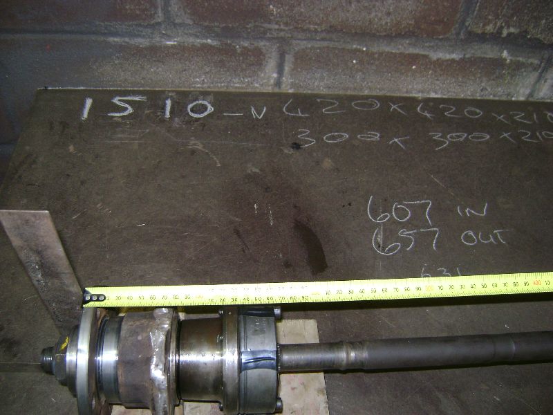 We moved our attention back to the suspension planning, first of all we assembled the suspension in a mock up form on a table to measure the track which ended at 1510mm without wheels for the combination of BMW and Ford part. One interesting part is the inner CV's/Lobro Joints, there bolt pattern is exactly the same as the BMW flanges, just the holes on the flanges sits at 10mm and the Lobro at 8mm, redrilling the Lobro's solved that problem. We build a suspension troubleshoot tool to help us determine the lengths of the upper and lower wishbones, after playing with a few different configuration we settled on getting the differential mounted as this is the most important part, then it will be ease to measure the lower wishbone length at it is the one that determines were the wheel wil sit. The upper one we can move around as we se fit to get the desired effect on camber and travel. A lower differential frame was designed, while keeping in mind the mountings of the lower control arm and the ability to adjust toe on them and the amount of effort needed to remove the differential. 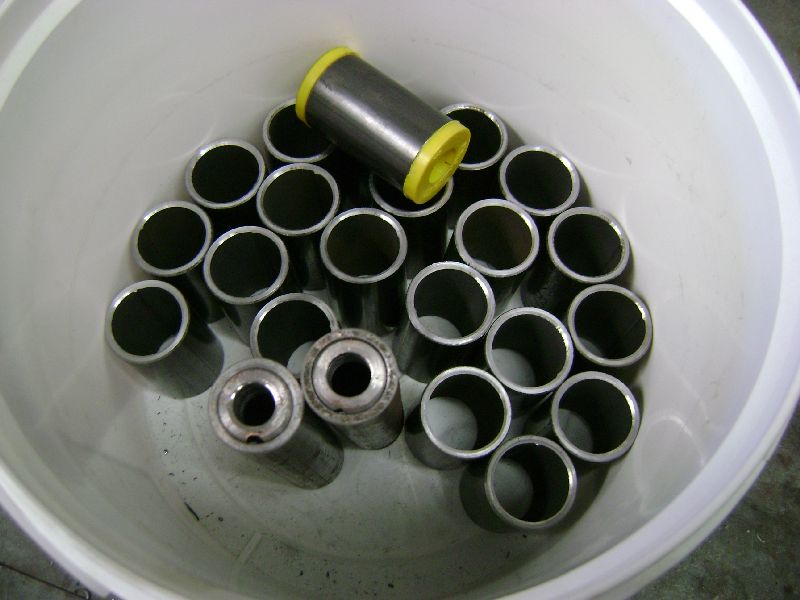 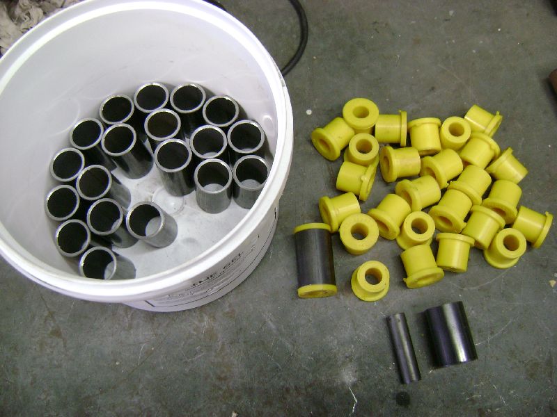 Over the weekend I got a lot of respect for any Fitter and Turner, it took me more or less 3 and a half hours to cut the outer wishbone pipes, machine down to 61mm and chamfer both sides inside and out, and another 30 mins on the lathe to dril 12mm holes in 4 pieces of MS shafting and machine down 2 pieces of pyp that will acts as spacers between the differentials upper mounts and top plate.  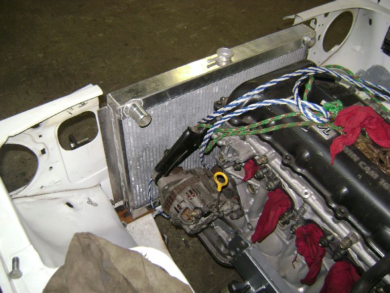  Since the radiator and oil cooler arrived, I could not resist the temptation to do a quick mock up install of it, just to make sure the radiator is the correct size this time round. Never in my life will I support the guys at The Radiator Specialist in Parow again. The first one took them a week to build, after I showed them that their reading skills was not up to par, as they read the 440mm cap fitted on the drawing as 480mm, it took them a month and a half to build a new one. But the best of the whole ordeal was the cheak of the owner telling me that I need to get a buyer for the one they build to big after I supplied them with a drawing that they obviously mis read or just ignored. Do we as clients really need to think for the experts in their field to these days, there is just no proud in workmanship anymore, non what so ever. To add to it, the second one was manhandled, the core is full of marks, I will need to sit down with a screw driver and correct it. I can write a book about this place, but lets leave it there and not support them again. The radiator made as the drawing stated was perfect, some people just have the ability to use a measurement instrument, the bonus of the custom made unit is that the top water hose will only require a 90 degree pipe. We then noticed the ideal placement for the oil cooler, on the right hand side next to the radiator. This will keep piping to a minimum and the routing of them will also be allot easier. A few other parts also arrived since the last visit, for a whole month I only collected parts and no work was done. 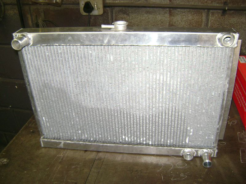 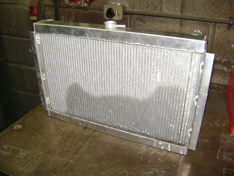 1. Custom Made Aluminium Radiator Length 620mm x Height 440mm without a cap, basically the biggest I can fit to the Datsun. The workmanship on the unit is very good, but the way they handle parts is shame, better packaging would have prevented a lot of the marks on the core. 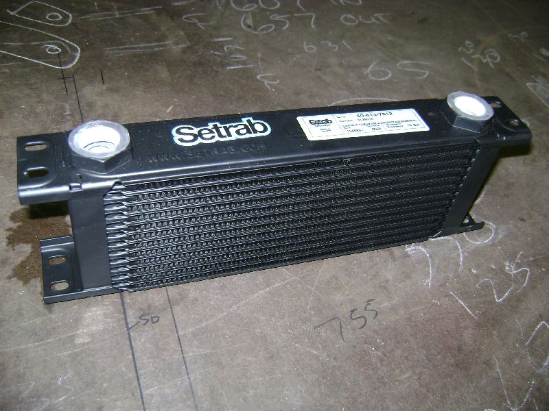 2. Setrab 13 row Oil Cooler, 330x99x50mm with M22x1.5 - female fittings. The only available oil cooler in South Africa that you can decide which fittings you want to use on and that was the correct size to fit my application. 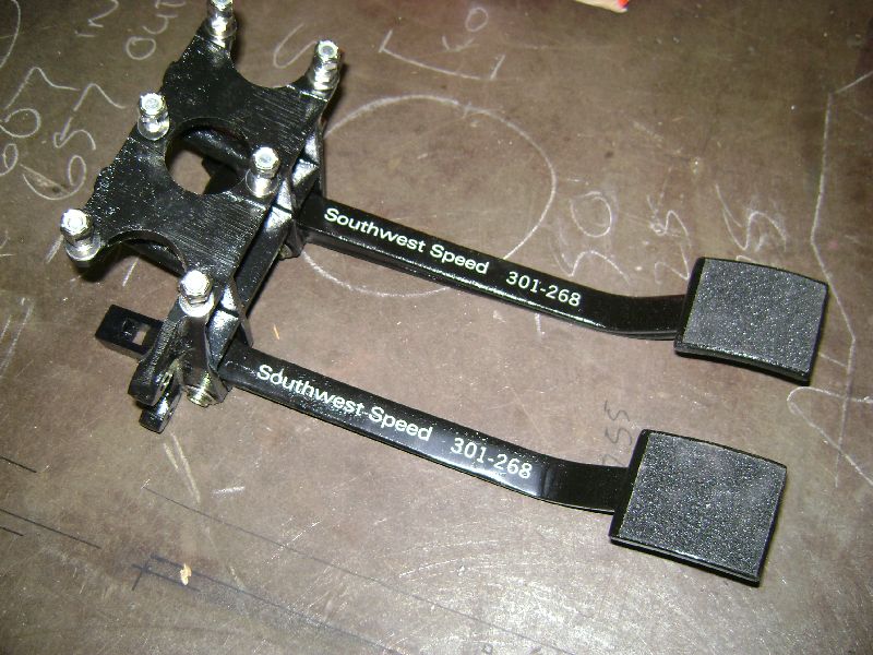 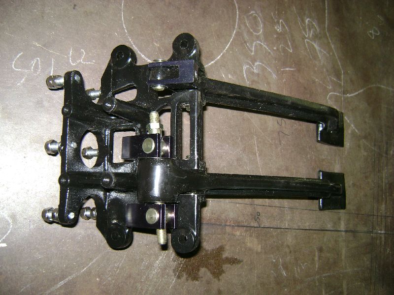 3. Reverse Swing PedalBox from Southwest Speed in the States. This piece of kit comes with brake and clutch pedal. Mountings for 3 Master Cylinders, 2 for the brakes, one rear, one front with adjustable balance bar and one for a hydraulic clutch 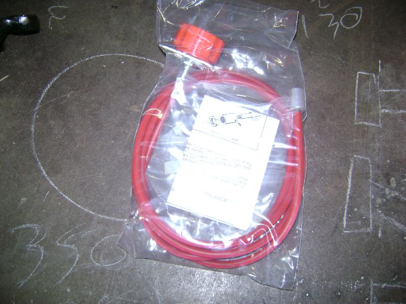 4. Brake Bias Adjustor - Cable Type that fits the above mentioned PedalBox
Posted on: 2010/8/2 8:34
Edited by racetech on 2013/12/24 6:27:07
|
|
|
|
|
Re: racetech's 1200 SR20VE Project |
|
Home away from home 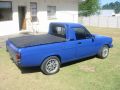
Joined:
2003/2/17 16:54
From Kingsley, Perth, WA
Group:
Registered Users
|
Racetech, check that diff ratio out carefully boet, 3.6:1 seems a little long for your setup even if you running 13 inch wiele. What rpm does that motor come on power? I had issues with my bakkies diff ratio and that was a 4,3:1 with 15 inch wheels (65 profile). The gaps between the gears were just too wide. But then again my setup only came onto boost about 4200rpm. Are you going to use it for gymkhana or track (circuit).Heres a link for a good gear ratio calcumalator http://www.osella.com.au/gear-ratios.htm
Posted on: 2010/8/2 9:05
|
|
|
|
|
Re: racetech's 1200 SR20VE Project |
|
Home away from home Joined:
2009/4/16 10:37
From Cape Town, South Africa
Group:
Registered Users
|
Gymkhana mainly, want to start competing in All Tar Rally's next year. Power starts from 2700. The biggest issue is that I am changing so much components and do not know what to expect, I just need to start somewhere and fine tune from there. In my ute I'm running a 3.89 final and it is quite good, once this vehicle is in competition I'll start tuning it.
Posted on: 2010/8/2 9:25
|
|
|
|
|
Re: racetech's 1200 SR20VE Project |
|
Home away from home Joined:
2003/2/17 16:54
From Kingsley, Perth, WA
Group:
Registered Users
|
Its gonna have a nice long first gear, which I suppose is what you need for gymkhana
Posted on: 2010/8/2 9:48
|
|
|
|
|
Re: racetech's 1200 SR20VE Project |
|
Home away from home Joined:
2009/4/16 10:37
From Cape Town, South Africa
Group:
Registered Users
|
I worked it out to more or less 70km/h in 1st at 8k rpm, where my ute is doing 58.1km/h in 1st at 7.5k rpm.
Posted on: 2010/8/2 9:57
|
|
|
You can view topic.
You cannot start a new topic.
You cannot reply to posts.
You cannot edit your posts.
You cannot delete your posts.
You cannot add new polls.
You cannot vote in polls.
You cannot attach files to posts.
You cannot post without approval.
|


;)
;)
;)
;)
;)
;)
;)
 Transfer

;)
;)
;)
;)
;)
;)
;)
;)
;)
;)
;)
;)
;)
;)
;)
;)
;)
;)
;)
;)
;)
;)
;)
;)
;)
;)
;)
;)
;)
;)
;)
;)
;)
;)
;)
;)
;)
;)
;)
;)
;)
;)
;)
;)
;)
;)
;)
;)
;)
;)
;)
;)
;)
;)
;)
;)
;)
;)
;)
;)
;)
;)
;)
;)
;)
;)
;)
;)
;)
