User Login    
 + Register
  • Main navigation
Login
Username:

Password:


Lost Password?

Register now!
Fast Search
Slow Search
Google Ad


Browsing this Thread:   3 Anonymous Users


« 1 ... 4 5 6 (7) 8 9 10 ... 30 »


Re: racetech's 1200 SR20VE Project
Home away from home
Joined:
2009/4/16 10:37
From Cape Town, South Africa
Group:
Registered Users
Posts: 803
Offline
17 September 2010 – Shock Mountings

Open in new window

Open in new window

Open in new window

Open in new window

Open in new window

Open in new window


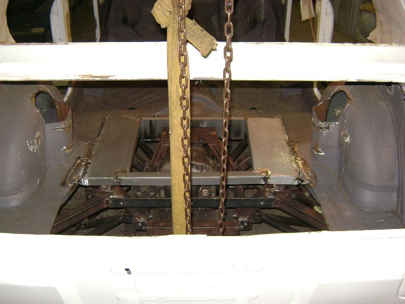
First order of business was to inspect the flooring over the differential that my father finished in the previous week. I was very stunned when I saw the car and figured out he finished the flooring, it really helped a lot as we could start work on the rear shock mounts. This particular piece of flooring had to be done before we could finish with the mounts.

Open in new window

Open in new window

Open in new window

Open in new window

Open in new window

Open in new window

Open in new window


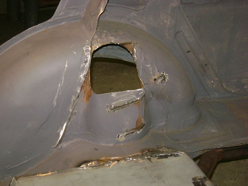
Friday evening we started work with the grinder. We are joking these days that whenever I arrive home on a Friday evening early, the poor car gets cut to bits. Well we got to work and started cutting the old shock towers open, these have been opened enough to allow springs with a outside diameter of 100mm to fit, move and still have clearance around it. We had to cut these open as we have no other way tan mounting the shocks on top of the uprights, the old opening was just not good enough as our shocks will be on a different angle than the old ones that mounted on the rear of the differential. We also wanted to mount the shocks higher than original to accommodate a shock with a longer stroke to enable me to use longer springs which in return would mean I can have môre body roll and the springs would still push the wheel into the ground. Fitting a limited slip differential does not solve everything.

Open in new window

Open in new window

Open in new window

Open in new window


Saturday morning started with the preparation work on all the bits and pičces of metal that would be used to finish the job, these included a combination of lazer cutted parts and bended sheet metal. Due to the fact that the flooring over the rear suspension was done, we started with the addition of another two brackets for the differential frame, these two will add support in the middel part of the frame and eliminate even môre vibrations.

Open in new window

Open in new window


During the course of the morning I started having a look at different options available to design the roll cage. It didn’t take long before I realized I will need to remove the roof lining to get a beter picture of the main bars running from the front to the rear. The roof lining was removed easier than I originally anticipated it would be. Know I will be able to draw the cage on paper and let MSA have a look at it and approve it, if not, at least tell me what is wrong or needed.

Open in new window

Open in new window

Open in new window

Open in new window


The tray between the rear pillars that houses the speakers was removed to enable us to strengthen that part of the vehicle, we formed some bended sheet metal to fit the car, luckily we managed to use the rear seat belt bolt location also in these parts, this is always considered to be a very strong part on a car. We then welded a lateral support to the main unit which in turn gets bolted to the frame. These lateral supports would also be used as a possible mounting spot for the main bars of the roll cage. These pieces would vorm the basis of the shock mounts, main roll cage bars and would need to be very strong, hence we fixed it with 10 M8 HT bolts per side and the seat belt bolt.

Open in new window

Open in new window


The shock mounting plates for the uprights was drilled and tacked in place, you would notice that I added 3 different shock mounting positions on the bottom, this would enable me to quickly adjust the ride height between 13” slicks, 14” semi slicks and 14” gravel or road tires.

Open in new window

Open in new window

Open in new window

Open in new window

Open in new window


We used a piece of 42 x 3mm round tubing for the bar between the main shock mounts, this unit was bolted and not welded in place, this would enable us to remove it in the future for alterations or in the case of major work on the rear end. We then proceeded with building some downwards supports, which is fixed to the differential cage middle mounting location. In this configuration the rear end of the vehicle is much stronger and stiffer than original. A added bonus is that with this design there is no need for a rear strut brace, it is already incorporated.

Open in new window

Open in new window

Open in new window

Open in new window

Open in new window


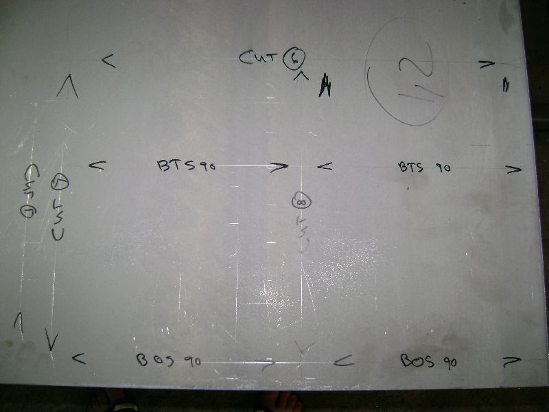
Sunday morning I started work on the remote reservoir bottles that will be used for the 2 brake master cylinders and clutch unit. This is in fact part of only a handful of original Datsun parts that will still be used, the main reason why I will spend so much time behind the lathe to machine the necessary parts for it. We also decided that we will replace the original Ford Sapphire rear wheel. The units in questioned is from the Volkswagen Golf MKII/III front wheel bearings, the hub carriers and hubs will be machined to accommodate these bearings as press in units and the cir clips as a lock. We also had time in the afternoon to design the rear boot box which will house the fuel cell, pumps, filters and surge tank. We finished the weekend of by completing the bend and cut layout on the 1.6mm electro galvanized sheet metal. This will be our first order of business on the next visit.

Posted on: 2010/9/22 8:22

Edited by racetech on 2013/12/24 6:16:46
_________________
Project Build: http://datsun1200.com/modules/newbb/viewtopic.php?topic_id=45104&forum=9

Don't find a problem, find a solution!!!!
www.race-tech.co.za
Transfer the post to other applications Transfer


Re: racetech's 1200 SR20VE Project
Home away from home
Joined:
2009/4/16 10:37
From Cape Town, South Africa
Group:
Registered Users
Posts: 803
Offline
24 September 2010 - Fuel Cell Holder & Power Steering Rack

Open in new window

Open in new window


Arrived home on Thursday evening due to the following day being a public holiday, didn’t take long to get in the groove and started the preparation work for the Fridays work. The main work set out for the weekend was the building of the Fuel Cell holder that had to be welded into the rear of the car and the mounting of the Toyota Cressida Power Steering rack. Thursday evening we managed to complete all the small cuts in the bended sheet metal and to bend all the lips that would be used for welding the holder in shape.

Open in new window

Open in new window


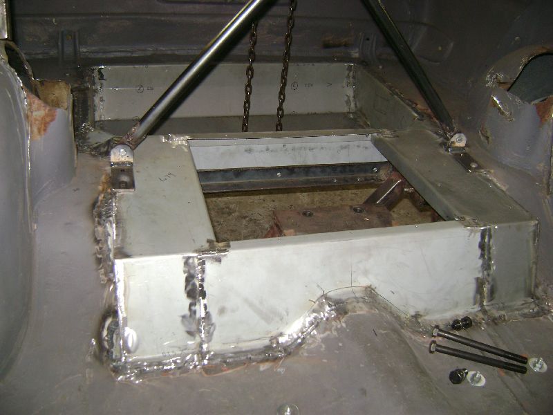
Friday morning was a early start to the day due to the amount of work that had to be done. We started to weld the main holder in place and then proceeded to cut it to the correct shape to fit between the rear of the car and the sub frame build for the suspension. We had to cut the front corners at a 45 degree angle to fit, this was then covered with separate pieces of sheet metal. The separate pieces also included a big lip which would cover the opening between holders front corners and the area between the original floor.

Open in new window

Open in new window

Open in new window

Open in new window

Open in new window


The building of the box kept us busy until lunch, afterwards we started tig welding the box into place, this kept us busy for quite a while. Once all the welding was done on the inside of the car my father started on the bottom. This gave me some breathing space to start the grinding of the welds on the inside in preparation for a coat of rust prevention and sealant. During this time I finished up with me machine work on the lathe for the remote mount reservoir containers. While my work was done and had some time on my hands, I tried my hand at being creative, one department where I’m severely lacking, free hand sketches. Managed to at least get a sequence of sketches done of the planned roll cage. I must admit, these sketches is almost something I need to classify as secret, I do not think anyone else will be able to understand them. Due to the nature of the sketches I decided to be on the safe side and take some pictures in black & white to draw the roll cage in to make it môre understandable for someone else.

Open in new window

Open in new window

Open in new window

Open in new window

Open in new window

Open in new window

Open in new window

Open in new window

Open in new window

Open in new window

Open in new window


Saturday morning started of by measuring the old suspension, afterwards we stripped the old steering box, idler arm and linkages. The cross member was removed and cleaned. First of we removed the old strengthening stripes on the cross member and replaced them with a bigger piece of sheet metal to add strength to the unit and enable us to weld some rack mounts to it. The cross member was coated with a rust prevention paint before we added the metal sheet to it. The cross member was reinstalled to the car with the lower wishbones in place, then the measuring started to get the rack in the correct position. Everything was marked and measured and the cross member again removed, this cross member was probably removed about 5 times to make sure everything fits in the space available during the whole process, space is quite limited between the cross member and the SR motor, but still môre than enough to make this work. We build the rack mounts with the correct spacing to get the as close as possible to the desired or original horizontal angles when the car is lowered to ride height. On the bench everything was calculated and positioned and the rack mounts was welded to the cross member. Manufactured some mounts to secure the rack to the cross member. Reinstalled the cross member and wishbones, placed the rack on the mounts, made sure it is in position and marked their position. Removed everything and drilled the holes. Once all was done everything was bolted back to the car, the only minor problem that we have with the rack is the front to back position. The rack is about 10 – 20mm môre to the front than the steering arm on the struts. This will be fixed by moving the rack another 10mm to the rear. This will be done by getting a new feed line made and rerouting it, by doing this we gain the extra 10mm. The rest will be gained by adjusting the track rods to pull the struts forward. Castor will be added on the bottom and also wheelbase, this means I will need to adjust less castor on the top castor / camber plates. I finished of the day’s work by grinding the bottom welds of the fuel cell holder, in order to do some painting the next morning on the underside, managed to squeeze some last bit of energy out to paint the inside welds of the holder.

Sunday morning started of with a paint brush in hand, painted all the welds on the underside of the car. Moved to the inside and sealed all the seams with polyurethane sealer. This kept me busy until lunch. Later the afternoon I returned to the workshop and started documenting bolts and nuts needed, created a complete inventory of parts that has to go for electro plating.

Work planned for the next visit would be one of the following or a combination, mount the radiator and oil cooler, refit the front radiator support or fit a steering column if I’m able to source one.

Posted on: 2010/9/28 10:34

Edited by racetech on 2013/12/24 6:13:48
_________________
Project Build: http://datsun1200.com/modules/newbb/viewtopic.php?topic_id=45104&forum=9

Don't find a problem, find a solution!!!!
www.race-tech.co.za
Transfer the post to other applications Transfer


Re: racetech's 1200 SR20VE Project
Guest_
awesome skills in this build.

Posted on: 2010/9/28 12:17
Transfer the post to other applications Transfer


Re: racetech's 1200 SR20VE Project
Home away from home
Joined:
2009/12/2 3:52
From Central Coast NSW
Group:
Registered Users
Posts: 239
Offline
very good read
planning to dump a fwd ve into my sss to replace the de when it blows
seems like a lot of hassle when you could of gone s14 or s15 n/a engine , same vvt and already rwd , some even coming with a 6 speed.
the fwd n1 pulsar one is supposed to have 180-200hp but its a very rare engine. all ones ive come across are just neos from primera(pulsars)
i would of gone s14/15 sr20ve but the rocker cover slants back at the end which leaves less room for me keeping the top of my firewall standard.

crazy build tho , very jealous.
i need more coins to get mine like yours.

Posted on: 2010/9/28 12:50
Transfer the post to other applications Transfer


Re: racetech's 1200 SR20VE Project
Home away from home
Joined:
2009/4/16 10:37
From Cape Town, South Africa
Group:
Registered Users
Posts: 803
Offline
In RSA the S14 and S15 motors is Turbo, I'm not a big turbo fan. The 6speed I know is not that strong as the 5speed. I don't think I will need more power than the standard ve with itb's on, but maybe if the need is there I'll source a set of sr16ve n1 cams and pistons.

Posted on: 2010/9/28 13:16
_________________
Project Build: http://datsun1200.com/modules/newbb/viewtopic.php?topic_id=45104&forum=9

Don't find a problem, find a solution!!!!
www.race-tech.co.za
Transfer the post to other applications Transfer


Re: racetech's 1200 SR20VE Project
Home away from home
Joined:
2009/4/16 10:37
From Cape Town, South Africa
Group:
Registered Users
Posts: 803
Offline
unfamilia, so whats your thoughts on the final rear suspension. just need to sort out the rear stabilizer bar.

Posted on: 2010/9/28 13:19
_________________
Project Build: http://datsun1200.com/modules/newbb/viewtopic.php?topic_id=45104&forum=9

Don't find a problem, find a solution!!!!
www.race-tech.co.za
Transfer the post to other applications Transfer


Re: racetech's 1200 SR20VE Project
Home away from home
Joined:
2009/12/2 3:52
From Central Coast NSW
Group:
Registered Users
Posts: 239
Offline
forgot you were in SA sorry.
in aus plently of front cut and engines that are n/a s14 and s15
i cant have turbo because im on my ps anyway.
and cant register a sr20det.(without money and shonky friends)
yeh hard to find cams for the ve , apparantrly stock ones are best.

yeh should go well.
in SA you have the nissan sabre ( a rebadged version of the australian pulsar. if you didnt know what i was talking about haha)

cheers anyway , enjoying the build , gives me hope for mine.

Posted on: 2010/9/28 13:24
Transfer the post to other applications Transfer


Re: racetech's 1200 SR20VE Project
Home away from home
Joined:
2009/12/2 3:52
From Central Coast NSW
Group:
Registered Users
Posts: 239
Offline
i dont see a 6 speed blowing behind a de
maybe turbo but not de
also quad throttles for mine are a deffinette.

Posted on: 2010/9/28 13:28
Transfer the post to other applications Transfer


Re: racetech's 1200 SR20VE Project
Home away from home
Joined:
2004/8/30 11:04
From Christchurch
Group:
Registered Users
Posts: 405
Offline
Good work. Its coming along nicely. I'm also building a sr20ve 1200 sedan race car over here in NZ. I'm not quite going to the extent you are though!!
A little bit of advice personally i'd leave the rack where it is. If you move it back you in line with your steering arm you will get rid of all your ackerman angle and although you don't want much on a race car it is beneficial to have a little. In plan view you should have a little forward angle on the tie rod going from the steering arm to the inner rack pivot point.
Ackerman angle is the difference in angle between the inside and outside wheel when turning. The more ackerman angle you have the more the inside wheel turns in relation to the outside. On a race car not much is needed as generally only a little steering input is used (in comparison to a little car that spends most its life in shopping car parks)

Posted on: 2010/9/28 22:57
Transfer the post to other applications Transfer


Re: racetech's 1200 SR20VE Project
Home away from home
Joined:
2009/4/16 10:37
From Cape Town, South Africa
Group:
Registered Users
Posts: 803
Offline
nick_m, thanks

I thought about that, what do you recommend the offset between rack and steering arms be?

I'll measure the current offset and let you know!

Posted on: 2010/9/29 9:12
_________________
Project Build: http://datsun1200.com/modules/newbb/viewtopic.php?topic_id=45104&forum=9

Don't find a problem, find a solution!!!!
www.race-tech.co.za
Transfer the post to other applications Transfer


« 1 ... 4 5 6 (7) 8 9 10 ... 30 »


You can view topic.
You cannot start a new topic.
You cannot reply to posts.
You cannot edit your posts.
You cannot delete your posts.
You cannot add new polls.
You cannot vote in polls.
You cannot attach files to posts.
You cannot post without approval.

[Advanced Search]