![[Datsun 1200 encyclopedia]](/wiki/upload/wiki.png)
| Revision as of 04:41, 11 January 2010 ddgonzal (Talk | contribs) (->Pinouts) <- Previous diff |
Current revision ddgonzal (Talk | contribs) (->Relay) |
||
| Line 1: | Line 1: | ||
| - | Datsun B110 headlights are fused through the fuse box. <b>No relays are used</b>. Original Specs for headlights are 50/40 watt (standard large round headlights). From the fuse box "Battery" side (always hot, not dependent on ignition key position), through a 15-amp fuse the circuit goes to the Light Switch. From the Light Switch it goes to the Dimmer switch on the column. From here -- depending on the position of the Dimmer lever position -- it goes to either the low (DIM) beam of the headlights or the high (MAIN) beam of the headlights. | + | Datsun B110 [[headlights]] are fused through the fuse box. <b>No relays are used</b>. Original Specs for headlights are 50/40 watt (standard large round headlights). From the fuse box "Battery" side (always hot, not dependent on ignition key position), through a 15-amp fuse the circuit goes to the Light Switch. From the Light Switch it goes to the Dimmer switch on the column. From here -- depending on the position of the Dimmer lever position -- it goes to either the low (DIM) beam of the headlights or the high (MAIN) beam of the headlights. |
| Also see: [[Headlight Specifications]] | Also see: [[Headlight Specifications]] | ||
| Line 9: | Line 9: | ||
| So the headlight circuit has these components: | So the headlight circuit has these components: | ||
| - | * Two identical headlights | + | * Two identical [[Headlights]] |
| *: (Standard 12V "large round" type used by all makes of older vehicles) | *: (Standard 12V "large round" type used by all makes of older vehicles) | ||
| - | * 15A Fuse in fuse box | + | * 15A Fuse in [[Fuse Box]] |
| - | * Light Switch | + | * [[Lighting Switch|Light Switch]] |
| - | * Dimmer switch (T/S & Light Switch on steering column) | + | * Dimmer Switch (T/S & Light Switch on steering column) |
| * High-beam indicator lamp in instrument panel | * High-beam indicator lamp in instrument panel | ||
| * Wiring and connectors | * Wiring and connectors | ||
| Line 19: | Line 19: | ||
| = Earthing = | = Earthing = | ||
| - | The headlights are grounded via the main wiring harness. | + | The headlights are grounded via the main engine room wiring harness. The harness includes a body ground point (at the horn relay) and an engine ground (at the alternator E terminal). |
| + | {{Album|23422}} | ||
| - | = Pinouts = | + | Unlike some earlier Datsuns, the 1200 does not use a switchable earth in the headlight circuit. |
| - | Light Switch connector | + | |
| - | <table width=400 border=1 borderwidth=1 bordercolor=black cellspacing=0 cellpadding=2> | + | <blockquote>Datsun 510 and early 620 use switchable ground. See [[620 Headlight Wiring]]</blockquote> |
| - | <tr bgcolor="ccccff"><td>R</td><td>Headlight hot feed Input | + | |
| + | = Headlight Socket = | ||
| + | Headlight socket<table class="wiki_table"> | ||
| + | <tr><td>B</td><td>Ground</td><td>body connection</td></tr> | ||
| + | <tr><td>RW</td><td>(high beam) to one RW terminal of Dimmer Switch</td><td>only powered if Dimmer lever is forward</td></tr> | ||
| + | <tr><td>RB</td><td>(low beam) to RB terminal of Dimmer switch</td><td>only powered if Dimmer lever is back</td></tr></table> | ||
| + | |||
| + | = Light Switch = | ||
| + | RHD and LHD use the same [[Lighting Switch]] with a 6-spade-connector. But for LHD applications the wiring harness only connects to four pins. | ||
| + | |||
| + | 4-connector Headlight Switch is powered. The Fusebox feeds it | ||
| + | |||
| + | 6-connector Headlight Switch is non-powered. The T/S switch inputs power to it. | ||
| + | |||
| + | == RHD == | ||
| + | 6-connectors wired. Note that low beams will work in POS 1, while high beams only work in POS 2 (knob pulled all the way out). | ||
| + | |||
| + | {{Album|10046}} | ||
| + | <br>With the knob pushed in, no circuits are connected. | ||
| + | <br>With knob pulled out to Position one (POSH) you are simply smashing | ||
| + | <br>With knob pulled out to Position two (POLL) you are just common | ||
| + | <br>With knob TWISTED (Australia Only), the dash lights are bright or dim | ||
| + | |||
| + | Australia has an extra wire coming off the side of the switch (for a total of seven wires). | ||
| + | |||
| + | == LHD == | ||
| + | 4-connectors wired up -- all Left-hand drive markets. | ||
| + | |||
| + | {{Album|21187}} | ||
| + | <br>With the knob pushed in, no circuits are connected. | ||
| + | <br>With knob pulled out to Position one, the parking lamps are activated | ||
| + | <br>With knob pulled out to Position two, parking + headlights are activated | ||
| + | |||
| + | Position Connections<table class="wiki_table"> | ||
| + | <tr><td>OFF</td><td>no connections</td></tr> | ||
| + | <tr><td>Pull stop 1 (halfway out)</td><td> | ||
| + | * GL to GL (parking lights)</td></tr> | ||
| + | <tr><td>Pull stop 2 (all the way out)</td><td> | ||
| + | * GL to GL (parking lights) | ||
| + | * R to R (headlights)</td></tr> | ||
| + | </table><br> | ||
| + | |||
| + | Light Switch connector<table class="wiki_table"> | ||
| + | <tr><td>R</td><td>Headlight hot feed Input | ||
| * from R wire of fuse box ('L' terminal)</td></tr> | * from R wire of fuse box ('L' terminal)</td></tr> | ||
| <tr><td>R</td><td>Headlight circuit hot Output | <tr><td>R</td><td>Headlight circuit hot Output | ||
| * To RY wire of Dimmer Switch</td></tr> | * To RY wire of Dimmer Switch</td></tr> | ||
| - | <tr bgcolor="ccccff"><td>n/a</td><td>no connection</td></tr> | ||
| <tr><td>n/a</td><td>no connection</td></tr> | <tr><td>n/a</td><td>no connection</td></tr> | ||
| - | <tr bgcolor="ccccff"><td>GL</td><td>parking lights hot feed | + | <tr><td>n/a</td><td>no connection</td></tr> |
| + | <tr><td>GL</td><td>parking lights hot feed | ||
| * from GL wire of fuse box ('PT' terminal)</td></tr> | * from GL wire of fuse box ('PT' terminal)</td></tr> | ||
| <tr><td>GL</td><td>parking lights circuit output | <tr><td>GL</td><td>parking lights circuit output | ||
| Line 37: | Line 81: | ||
| * to GL wire of running (parking) lights | * to GL wire of running (parking) lights | ||
| * to GL wire of Instrument panel</td></tr> | * to GL wire of Instrument panel</td></tr> | ||
| - | </table> | + | </table><br> |
| - | light switch wiring diagram | + | = Low/High Beam Circuit - 4-pole = |
| - | <br>[http://datsun1200.com/modules/myalbum/photo.php?lid=10046 http://ddgonzal.members.winisp.net/getThumb.aspx?width=400&uri=http://datsun1200.com/modules/myalbum/photos/10046.jpg] | + | For simple 4-connector light switch ONLY |
| + | {{Album|21188}} | ||
| + | <br>With the T/S lever pulled back, power goes to Low beams | ||
| + | <br>With the T/S lever pushed forward, power goes to High beams | ||
| - | Position Connections<table border=1 borderwidth=1 bordercolor=black cellspacing=0 cellpadding=2> | + | Dimmer Switch (in T/S & Light Switch unit on steering column, only headlight section of switch listed here)<table class="wiki_table"> |
| - | <tr bgcolor="ccccff"><td>OFF</td><td>no connections</td></tr> | + | |
| - | <tr><td>Pull stop 1 (halfway out)</td><td> | + | |
| - | * GL to GL (parking lights)</td></tr> | + | |
| - | <tr><td>Pull stop 2 (all the way out)</td><td> | + | |
| - | * GL to GL (parking lights) | + | |
| - | * R to R (headlights)</td></tr> | + | |
| - | </table> | + | |
| - | + | ||
| - | + | ||
| - | Headlight connector<table border=1 borderwidth=1 bordercolor=black cellspacing=0 cellpadding=2> | + | |
| - | <tr><td>B</td><td>Ground</td><td>body connection</td></tr> | + | |
| - | <tr><td>RW</td><td>(high beam) to one RW terminal of Dimmer Switch</td><td>only powered if Dimmer lever is forward</td></tr> | + | |
| - | <tr><td>RB</td><td>(low beam) to RB terminal of Dimmer switch</td><td>only powered if Dimmer lever is back</td></tr></table> | + | |
| - | + | ||
| - | + | ||
| - | Dimmer Switch (in T/S & Light Switch unit on steering column, only headlight section of switch listed here)<table border=1 borderwidth=1 bordercolor=black cellspacing=0 cellpadding=2> | + | |
| <tr><td>RY</td><td>Headlight hot feed</td><td> | <tr><td>RY</td><td>Headlight hot feed</td><td> | ||
| * From R wire of Light Switch</td></tr> | * From R wire of Light Switch</td></tr> | ||
| Line 68: | Line 99: | ||
| * To RY wire of "MB" light\* in Instrument panel</td></tr> | * To RY wire of "MB" light\* in Instrument panel</td></tr> | ||
| </table>\* Labeled "Beam" for 1971. The other side of this light is grounded. | </table>\* Labeled "Beam" for 1971. The other side of this light is grounded. | ||
| + | <br> | ||
| + | = Low/High Beam Circuit - 6-pole = | ||
| + | For 6-connector headlight switch ONLY. | ||
| - | = Passing Light Switch = | + | Power from the [[Fuse Box]] Light circuit goes directly to the T/S switch. From there it is passed along to the Headlight switch and finally to the headlights. The headlight switch has seperate inputs for High and Low beams. |
| - | A passing light feature was an option for B110. If your turn-signal lever has a push-button on the end, it's the passing light switch. Push it in, and the headlights light while it's pushed in (regardless of whether lights are on or off). | + | |
| - | <br>This is composed of two parts: | + | B: earth/ground |
| - | * The switch itself is part of the turn signal (on the steering column). | + | RW: high beam |
| - | *: [http://datsun1200.com/modules/myalbum/photo.php?lid=14968 http://datsun1200.com/modules/myalbum/photos/thumbs/14968.jpg] [http://datsun1200.com/modules/myalbum/photo.php?lid=14971 http://datsun1200.com/modules/myalbum/photos/thumbs/14971.jpg] | + | RB: low beam |
| - | * The relay. 1200s don't use headlight relays, except for this optional Passing Switch. It looks very much like the Horn Relay. | + | RY: power input for T/S Switch |
| - | ** 25230-89912 RELAY-passing lamp (4-connector relay on early models) | + | R: Lighting fuse |
| - | ** 25230-89905 RELAY-passing lamp (3-connector relay from 1971 Apr) | + | |
| - | ** 26320-14800 RELAY-horn (has 3 connectors, located by Coil) | + | |
| - | **: [http://datsun1200.com/modules/myalbum/photo.php?lid=14969 http://datsun1200.com/modules/myalbum/photos/thumbs/14969.jpg] [http://datsun1200.com/modules/myalbum/photo.php?lid=14970 http://datsun1200.com/modules/myalbum/photos/thumbs/14970.jpg] | + | |
| + | {{Album|25097}} | ||
| + | = Passing Light Switch = | ||
| + | A passing light feature was an option for B110. | ||
| - | Note that this just wires in series with the standard wiring. From the 'L' fuse to the high-beam wiring, the switch bypasses simply the regular switch, firing the Main Beams. | + | {{SeeMainArticle|Passing_Lamp|14971}} |
| - | [http://datsun1200.com/modules/myalbum/photo.php?lid=5027 http://ddgonzal.members.winisp.net/getThumb.aspx?width=400&uri=http://datsun1200.com/modules/myalbum/photos/5027.jpg] | + | = Relay = |
| - | <br>Passing Light Switch circuit | + | Datsun 1200 doesn't use a headlight relay, instead full power goes through the lighting switch and the dash harness. But a serious peformance issue is that the main wiring goes through a 20-gauge [[Fusible Link]]. |
| - | * The red circle indicates the part of the T/S switch that is different from a normal T/S switch | + | |
| + | Headlights want a 14 gauge wire for the full voltage to reach the lights. If using high-power H4 lights, you might even go with yet even larger 12 gauge wire. There is no need to go any larger. The good news is that apparently '''Nissan already fitted 12-gauge wire!''' with 14-gauge for the low beams. So no need to replace the headlight sockets and wires, instead just add a relay to bypass the Fusible Link and feed in power through an extra Fuse. | ||
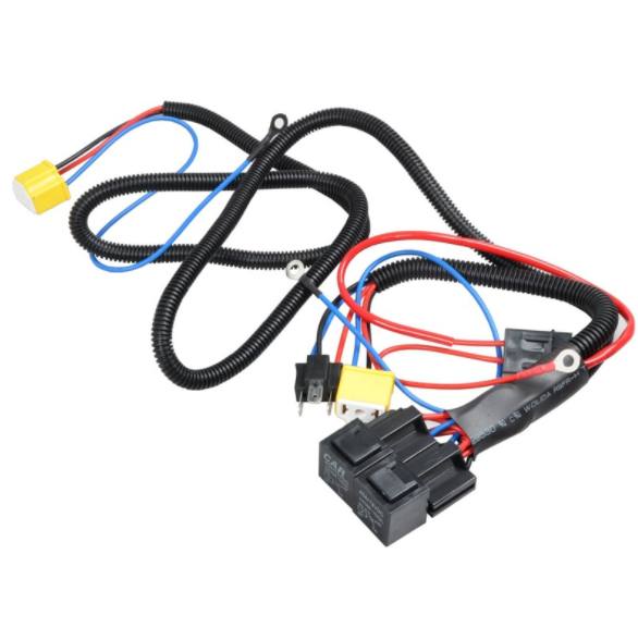
| + | Most cars use a headlight relay, to keep high power from going through the headlight and dimmer switches. You may add a relay to the Datsun 1200 to improve the power to the headlights. Some club members report the headlights are much brighter when wired up this way. | ||
| - | = Relay = | + | {{Album|14978}} |
| - | You may add a relay to improve the power to the headlights. Some club members report the headlights are much brighter when wired up this way. | + | |
| + | You can get 14-gauge connectors and wires, the fuses and lengths of wire from a wrecking yard. Or buy the parts new, which is easier. | ||
| - | [http://datsun1200.com/modules/myalbum/photo.php?lid=14978 http://ddgonzal.members.winisp.net/getThumb.aspx?width=220&uri=http://datsun1200.com/modules/myalbum/photos/14978.jpg] | + | [{{Post|254634}} Discussion] |
| - | [http://datsun1200.com/modules/newbb/viewtopic.php?topic_id=40186&forum=1&post_id=254634#forumpost254634 Discussion] | + | [{{Post|491749}} relay kit] less expensive than used parts |
| + | <br>{{UploadPost|174_5d0c702f1311a.jpg|491750}} | ||
| == Harness Kit == | == Harness Kit == | ||
| - | If you have more money than time, an Relay wiring kit is really easy: | + | If you have more money than time, a Relay wiring kit is really easy: |
| Take the new harness: | Take the new harness: | ||
| - | 1. Connect HOT wire | + | # Connect HOT wire |
| - | 2. Ground/earth the relays | + | # Ground/earth the relays |
| - | 3. Plug into existing headlight connector | + | # Plug into existing headlight connector |
| - | 4. Plug harness into headlights | + | # Plug harness into headlights |
| - | Your'e Done! Only $129 USD | + | # Comes with the proper fuses and will bypass the stock Fusible Link |
| + | You're Done! Only $129 USD [http://store.summitracing.com/partdetail.asp?autofilter=1&part=PRF%2D30815&N=700+400012+304711+115&autoview=sku Painless Wiring Headlight Harness with relays] | ||
| - | [http://store.summitracing.com/partdetail.asp?autofilter=1&part=PRF%2D30815&N=700+400012+304711+115&autoview=sku Painless Wiring Headlight Harness with relays] | + | == DIY == |
| + | Do it yourself. I recommend 14-gauge wire for Halogen, but you can use 12-gauge wire for H4 high-power headlights. 14-gauge can handle 24-32 amps for 10 foot (3 meter) length, which is plenty as Halogen H6204 high beams (two bulbs) draw only 12 amp maximum at 15V. The extra capacity will keep the voltage drop minimal. If the length of + and - wire is 10 ft total, expect 12A draw voltage drop to be 0.6V at 12V with 14 gauge wire and 0.4v with 12 gauge wire. | ||
| + | * 14-gauge wire for the HOT side (RED or whatever color you want) | ||
| + | * 14-gauge wire BLACK for the earth/ground side | ||
| + | * Headlight connectors with 14-gauge leads | ||
| + | * Two fuses (or circuit breakers?): | ||
| + | ** 15 amp for high beam Halogen 65W bulb x2 (up to 150W total) | ||
| + | ** 20 amp for H4s (up to 200W total) | ||
| + | ** 10amp for low beam (up to 100W per side) | ||
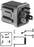
| + | * Two relays of 20A minimum rating, get a reliable OEM unit like this common Nissan part: | ||
| + | *: {{Thumb|21854}} | ||
| + | # Connect two short lengths of red wires to the BAT + or ALT + (your choice) | ||
| + | # Fix fuses to these two short HOT wires, to protect the rest of the new wiring | ||
| + | # Then more HOT to the Relays (D). Keep the wires as short as is feasible | ||
| + | # more HOT wire from relays to the headlight connectors | ||
| + | #: {{Thumb|22113}} | ||
| + | #* High-beam relay (B) to the new headlight connector 56a High-beam | ||
| + | #* Low-beam relay (B) to the new headlight connector 56b Low-beam | ||
| + | # Fix BLACK from new headlight connectors to a body ground or engine block | ||
| + | # Fix BLACK from Battery cable terminal to body ground (not needed if your Battery cable is already 12-gauge) | ||
| + | # connect small wires (20 gauge is fine) from one of the '''original''' headlight connectors to relays. Just leave the other connector alone. | ||
| + | #* One wire from 56b to the low-beam relay switch trigger (C) | ||
| + | #* another wire from 56a to the high-beam relay switch trigger (C) | ||
| + | # connect small black wire to ground both relays switch (E) | ||
| + | #: can ground it: | ||
| + | #:* to body, or | ||
| + | #:* to engine block, or | ||
| + | #:* or to 31 of original headlight connector | ||
| + | # To prevent corrosion, seal all the wire connection ends with a sealer (shrink-wrap) | ||
| - | [[Category:Body Electrical System]] | + | [[Category:Body Electrical System]]{{End}} |
Current revision
Datsun B110 headlights are fused through the fuse box. No relays are used. Original Specs for headlights are 50/40 watt (standard large round headlights). From the fuse box "Battery" side (always hot, not dependent on ignition key position), through a 15-amp fuse the circuit goes to the Light Switch. From the Light Switch it goes to the Dimmer switch on the column. From here -- depending on the position of the Dimmer lever position -- it goes to either the low (DIM) beam of the headlights or the high (MAIN) beam of the headlights.
Also see: Headlight Specifications
Contents |
Overview
The headlights are grounded via the main wiring harness.
Completing the headlight features is the "High Beam" light in the instrument panel. This is connected to the high-beam circuit to light up a visual indicator on the dash when the high beams are on.
So the headlight circuit has these components:
- Two identical Headlights
- (Standard 12V "large round" type used by all makes of older vehicles)
- 15A Fuse in Fuse Box
- Light Switch
- Dimmer Switch (T/S & Light Switch on steering column)
- High-beam indicator lamp in instrument panel
- Wiring and connectors
- Relays are NOT used
Earthing
The headlights are grounded via the main engine room wiring harness. The harness includes a body ground point (at the horn relay) and an engine ground (at the alternator E terminal).
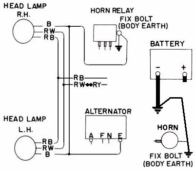
Unlike some earlier Datsuns, the 1200 does not use a switchable earth in the headlight circuit.
Datsun 510 and early 620 use switchable ground. See 620 Headlight Wiring
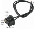
Headlight Socket
Headlight socket| B | Ground | body connection |
| RW | (high beam) to one RW terminal of Dimmer Switch | only powered if Dimmer lever is forward |
| RB | (low beam) to RB terminal of Dimmer switch | only powered if Dimmer lever is back |
Light Switch
RHD and LHD use the same Lighting Switch with a 6-spade-connector. But for LHD applications the wiring harness only connects to four pins.
4-connector Headlight Switch is powered. The Fusebox feeds it
6-connector Headlight Switch is non-powered. The T/S switch inputs power to it.
RHD
6-connectors wired. Note that low beams will work in POS 1, while high beams only work in POS 2 (knob pulled all the way out).
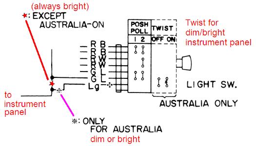
With the knob pushed in, no circuits are connected.
With knob pulled out to Position one (POSH) you are simply smashing
With knob pulled out to Position two (POLL) you are just common
With knob TWISTED (Australia Only), the dash lights are bright or dim
Australia has an extra wire coming off the side of the switch (for a total of seven wires).
LHD
4-connectors wired up -- all Left-hand drive markets.
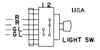
With the knob pushed in, no circuits are connected.
With knob pulled out to Position one, the parking lamps are activated
With knob pulled out to Position two, parking + headlights are activated
| OFF | no connections |
| Pull stop 1 (halfway out) |
|
| Pull stop 2 (all the way out) |
|
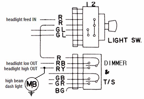
Light Switch connector
| R | Headlight hot feed Input
|
| R | Headlight circuit hot Output
|
| n/a | no connection |
| n/a | no connection |
| GL | parking lights hot feed
|
| GL | parking lights circuit output
|
Low/High Beam Circuit - 4-pole
For simple 4-connector light switch ONLY
With the T/S lever pulled back, power goes to Low beams
With the T/S lever pushed forward, power goes to High beams
| RY | Headlight hot feed |
|
| RB | headlight low-beam |
|
| RW | headlight high-beam |
|
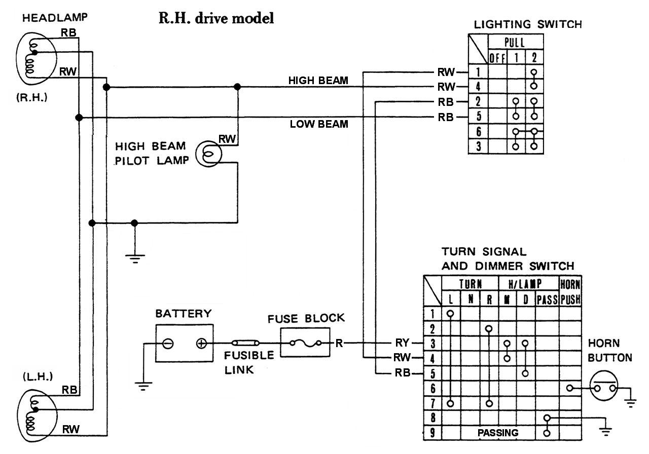
Low/High Beam Circuit - 6-pole
For 6-connector headlight switch ONLY.
Power from the Fuse Box Light circuit goes directly to the T/S switch. From there it is passed along to the Headlight switch and finally to the headlights. The headlight switch has seperate inputs for High and Low beams.
B:  earth/ground
RW: high beam
RB: low beam
RY: power input for T/S Switch
R: Lighting fuse
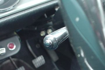
Passing Light Switch
A passing light feature was an option for B110.
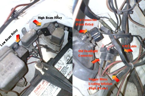
Relay
Datsun 1200 doesn't use a headlight relay, instead full power goes through the lighting switch and the dash harness. But a serious peformance issue is that the main wiring goes through a 20-gauge Fusible Link.
Headlights want a 14 gauge wire for the full voltage to reach the lights. If using high-power H4 lights, you might even go with yet even larger 12 gauge wire. There is no need to go any larger. The good news is that apparently Nissan already fitted 12-gauge wire! with 14-gauge for the low beams. So no need to replace the headlight sockets and wires, instead just add a relay to bypass the Fusible Link and feed in power through an extra Fuse.
Most cars use a headlight relay, to keep high power from going through the headlight and dimmer switches. You may add a relay to the Datsun 1200 to improve the power to the headlights. Some club members report the headlights are much brighter when wired up this way.
You can get 14-gauge connectors and wires, the fuses and lengths of wire from a wrecking yard. Or buy the parts new, which is easier.
POST relay kit less expensive than used parts
Harness Kit
If you have more money than time, a Relay wiring kit is really easy:
Take the new harness:
- Connect HOT wire
- Ground/earth the relays
- Plug into existing headlight connector
- Plug harness into headlights
- Comes with the proper fuses and will bypass the stock Fusible Link
You're Done! Only $129 USD Painless Wiring Headlight Harness with relays
DIY
Do it yourself. I recommend 14-gauge wire for Halogen, but you can use 12-gauge wire for H4 high-power headlights. 14-gauge can handle 24-32 amps for 10 foot (3 meter) length, which is plenty as Halogen H6204 high beams (two bulbs) draw only 12 amp maximum at 15V. The extra capacity will keep the voltage drop minimal. If the length of + and - wire is 10 ft total, expect 12A draw voltage drop to be 0.6V at 12V with 14 gauge wire and 0.4v with 12 gauge wire.
- 14-gauge wire for the HOT side (RED or whatever color you want)
- 14-gauge wire BLACK for the earth/ground side
- Headlight connectors with 14-gauge leads
- Two fuses (or circuit breakers?):
- 15 amp for high beam Halogen 65W bulb x2 (up to 150W total)
- 20 amp for H4s (up to 200W total)
- 10amp for low beam (up to 100W per side)
- Two relays of 20A minimum rating, get a reliable OEM unit like this common Nissan part:
-
- Connect two short lengths of red wires to the BAT + or ALT + (your choice)
- Fix fuses to these two short HOT wires, to protect the rest of the new wiring
- Then more HOT to the Relays (D). Keep the wires as short as is feasible
- more HOT wire from relays to the headlight connectors
- High-beam relay (B) to the new headlight connector 56a High-beam
- Low-beam relay (B) to the new headlight connector 56b Low-beam
-
- Fix BLACK from new headlight connectors to a body ground or engine block
- Fix BLACK from Battery cable terminal to body ground (not needed if your Battery cable is already 12-gauge)
- connect small wires (20 gauge is fine) from one of the original headlight connectors to relays. Just leave the other connector alone.
- One wire from 56b to the low-beam relay switch trigger (C)
- another wire from 56a to the high-beam relay switch trigger (C)
- connect small black wire to ground both relays switch (E)
- can ground it:
- to body, or
- to engine block, or
- or to 31 of original headlight connector
- can ground it:
- To prevent corrosion, seal all the wire connection ends with a sealer (shrink-wrap)