| Revision as of 02:27, 1 March 2022 ddgonzal (Talk | contribs) <- Previous diff |
Revision as of 02:42, 1 March 2022 ddgonzal (Talk | contribs) Next diff -> |
||
| Line 3: | Line 3: | ||
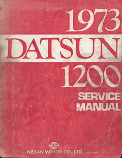
| Nissan factory service manual for the 1973 Datsun 1200, North America edition. | Nissan factory service manual for the 1973 Datsun 1200, North America edition. | ||
| - | [https://drive.google.com/file/d/0B0eVy1WCp6rZdVVjZWhzbkhJajA/view?usp=sharing&resourcekey=0-j__2LHwMdhv7tIB_ntUn8w DATSUN 1200 SERVICE MANUAL] MODEL [[B110]] SERIES NISSAN MOTOR CO., LTD. TOKYO, JAPAN | + | DATSUN 1200 SERVICE MANUAL MODEL [[B110]] SERIES NISSAN MOTOR CO., LTD. TOKYO, JAPAN |
| <br>{{AlbumH|14103}} | <br>{{AlbumH|14103}} | ||
| Line 49: | Line 49: | ||
| = ENGINE ELECTRICAL SYSTEM = | = ENGINE ELECTRICAL SYSTEM = | ||
| - | SECTION EE | + | [https://drive.google.com/file/d/0B0eVy1WCp6rZdVVjZWhzbkhJajA/view?usp=sharing&resourcekey=0-j__2LHwMdhv7tIB_ntUn8w SECTION EE ENGINE ELECTRICAL SYSTEM] |
| BATTERY EE-1 | BATTERY EE-1 | ||
| STARTING MOTOR EE-3 | STARTING MOTOR EE-3 | ||
| Line 61: | Line 61: | ||
| = BODY ELECTRICAL = | = BODY ELECTRICAL = | ||
| - | SECTION BE | + | [https://drive.google.com/file/d/0B0eVy1WCp6rZS182ODBLNmFBYms/view?usp=sharing&resourcekey=0-HZlISU6B-iO-LO7PC3XaPQ SECTION BE BODY ELECTRICAL] |
| BE-1 [[#WIRING]] | BE-1 [[#WIRING]] | ||
| BE-6 [[#FUSE]] | BE-6 [[#FUSE]] | ||
| Line 100: | Line 100: | ||
| CLUSTER LID BE-18 | CLUSTER LID BE-18 | ||
| - | {{Speedometer|SPEEDOMETER}} BE-19 | + | [[Speedometer|SPEEDOMETER]] BE-19 |
| FUEL GAUGE AND TEMPERATURE GAUGE BE-19 | FUEL GAUGE AND TEMPERATURE GAUGE BE-19 | ||
| OIL PRESSURE AND IGNITION WARNING LAMPS BE-20 | OIL PRESSURE AND IGNITION WARNING LAMPS BE-20 | ||
Revision as of 02:42, 1 March 2022
<-- back to Repair Manual
Nissan factory service manual for the 1973 Datsun 1200, North America edition.
DATSUN 1200 SERVICE MANUAL MODEL B110 SERIES NISSAN MOTOR CO., LTD. TOKYO, JAPAN

Contents |
Index
QUICK REFERENCE INDEX
GI GENERAL INFORMATION
ET EMISSION CONTROL AND TUNE-UP
EM #ENGINE MECHANICAL
EL ENGINE LUBRICATION SYSTEM
CO COOLING SYSTEM
EF FUEL SYSTEM
EE #ENGINE ELECTRICAL SYSTEM
ER ENGINE REMOVAL & INSTALLATION
CL CLUTCH
TM TRANSMISSION
AT AUTOMATIC TRANSMISSION
PD PROPELLER SHAFT & DIFFERENTIAL CARRIER
FA FRONT AXLE & FRONT SUSPENSION
RA REAR AXLE & REAR SUSPENSION
BR BRAKE
WT WHEEL AND TIRE
ST STEERING
FE ENGINE CONTROL FUEL & EXHAUST SYSTEM
BF BODY
BE #BODY ELECTRICAL
SE SERVICE EQUIPMENT
FORWARD
This service manual has been prepared for the purpose of assisting service personnel of authorized NISSAN/DATSUN dealers in providing effective service and maintenance of the 1973 Datsun 1200.
Since proper maintenance and service are absolutely essential in satisfying the owners of Datsun, this manual should be kept in a handy place for ready reference and should be carefully studied.
This manual includes procedures for maintenance adjustments, minor service operations, removal and installation, and for disassembly and assembly of components.
The #Quick Reference Index on the first page enable the user to quickly locate and desired section. At the beginning of each individual section is a table of contents, which gives the page number on which each major subject begins. An index is placed at the begining of each major subject within the section.
The #Special Tools, when required, presented at the "SE" section.
All information, illustration and specifications contained in this manual are based on the latest product information available at the time of publication approval.
Right for alternation of specifications and methods at any time are reserved.
NISSAN MOTOR CO., LTD.
TOKYO, JAPAN
(C) 1972 NISSAN MOTOR CO., LTD.
ENGINE MECHANICAL
ENGINE ELECTRICAL SYSTEM
SECTION EE ENGINE ELECTRICAL SYSTEM
BATTERY EE-1
STARTING MOTOR EE-3
CHARGING CIRCUIT EE-15
ALTERNATOR EE-16
REGULATOR EE-23
IGNITION CIRCUIT EE-29
DISTRIBUTOR EE-29
IGNITION COIL EE-36
SPARK PLUG EE-37
BODY ELECTRICAL
SECTION BE BODY ELECTRICAL
BE-1  #WIRING
BE-6  #FUSE
BE-7  #LIGHTING SYSTEM
BE-15 #HORN
BE-18 #METERS AND GAUGES
BE-26 #WINDSHIELD WIPER AND WASHER
BE-29 #IGNITION SWITCH AND STEERING LOCK
BE-31 #CLOCK
BE-32 #RADIO
BE-34 #HEATER
WIRING
BE-1 WIRING
WIRING HARNESS BE-1
  Engine Compartment harness BE-1
  Instrument harness BE-2
  Body harness BE-2
WIRING DIAGRAM BE-4
  Fig. BE-14 Wiring diagram for manual transmission model
  Fig. BE-15 Wiring diagram for automatic transmission model
INSPECTION BE-6
FUSE
BE-6 FUSE
LIGHTING SYSTEM
BE-7 LIGHTING SYSTEM
HORN
BE-15 HORN
METERS AND GAUGES
METERS AND GAUGES BE-18
CLUSTER LID BE-18
SPEEDOMETER BE-19
FUEL GAUGE AND TEMPERATURE GAUGE BE-19
OIL PRESSURE AND IGNITION WARNING LAMPS BE-20
HAND BRAKE WARNING LAMP BE-21
BULB SPECIFICATIONS BE-21
TROUBLE DIAGNOSES AND CORRECTIONS BE-22
  Speedometer BE-22
  Thermometer and fuel meter BE-23
  Oil pressure and ignition warning lamps BE-23
WINDSHIELD WIPER AND WASHER
BE-26 WINDSHIELD WIPER AND WASHER
IGNITION SWITCH AND STEERING LOCK
BE-29 IGNITION SWITCH AND STEERING LOCK
CLOCK
BE-31 CLOCK
RADIO
BE-32 RADIO
HEATER
BE-34 HEATER

![[Datsun 1200 encyclopedia]](/wiki/upload/wiki.png)